Showing posts with label Network Architecture. Show all posts

Friday, 20 June 2025

Understanding the Internet’s Hidden Infrastructure

Most people experience the Internet as a seamless service, but beneath that simplicity lies a multi-layered infrastructure made up of interconnected networks, routing policies, exchange points, and edge delivery platforms. These are the systems that keep global data flowing — reliably, efficiently, and at scale.

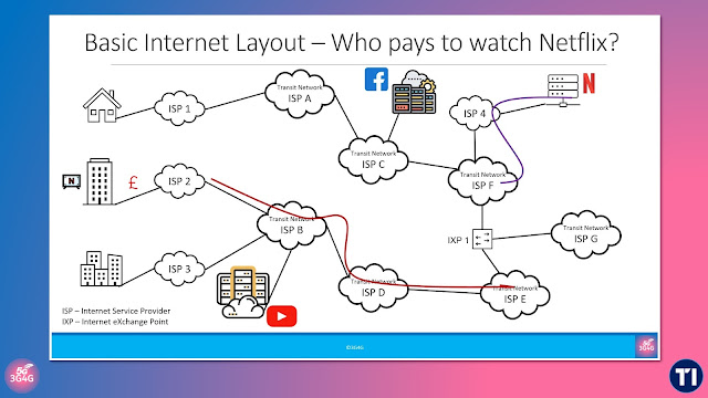
In our recent explainer video, we examine this invisible architecture by following the path of data from users to content providers and back again. The tutorial covers:

  • The hierarchical structure of Internet Service Providers (ISPs) and how they form transit chains by purchasing upstream connectivity
  • The use of Internet Exchange Points (IXPs) for settlement-free peering between networks, including the difference between public and private peering
  • The infrastructure behind Content Delivery Networks (CDNs) and the role of Netflix's Open Connect Appliances (OCAs)
  • The emerging importance of Multi-access Edge Computing (MEC) in localising compute and reducing backbone load

We also touch on real-world examples such as:

  • Swisscom’s temporary standoff with Netflix in 2016, highlighting the commercial tensions in peering agreements
  • The more recent regulatory intervention by ComCom, requiring Swisscom to establish zero-settlement peering with Init7

These cases demonstrate how infrastructure policy, competitive pressure, and traffic engineering come together to shape the performance and openness of the Internet.

Watch the video below to better understand the physical and logical structures that underpin our digital world:

Whether you're in network planning, architecture, or policy, this video offers a concise look at the building blocks that make the Internet work.

You can download the slides from here.

Related Posts

Friday, 19 February 2021

Open RAN (O-RAN) RRU (O-RU) and DU (O-DU) Design


We often publish Open RAN related information on this blog. Now, Telefónica has just published a whitepaper providing an overview of the main technology elements that it is developing in collaboration with selected partners in the Open RAN ecosystem. 

It describes the architectural elements, design criteria, technology choices and key chipsets employed to build a complete portfolio of radio units and baseband equipment capable of a full 4G/5G RAN rollout in any market of interest. More details here and the PDF is here.

The following is a selective abstract from the paper:

Sites within Telefónica footprint can be broadly classified into four types, from low/medium capacity 4G to high/dense capacity 4G+5G, as illustrated in Figure 1. Each of those types correspond to a particular arrangement of DUs and RRUs whose design and dimensioning represents a key milestone that must be achieved prior to any further development. Representative frequency bands are just shown for illustration purposes, as well the number of cells that can be typically found in each site type.

3GPP defined a new architectural model in Release 15, where the gNB is logically split into three entities denoted as CU, DU and RRU. The RAN functions that correspond to each of the three entities are determined by the so-called split points. After a thorough analysis of the potential split options, 3GPP decided to focus on just two split points: so-called split 2 and split 7, although, only the former one was finally standardized. The resulting partitioning of network functions is shown in Figure 2.

The CU (Centralized Unit) hosts the RAN functions above split 2; the DU (Distributed Unit) runs those below split 2 and above split 7; and the RRU hosts the functions below split 7 as well as all the RF processing.

The O-RAN Alliance further specified a multi-vendor fronthaul interface between the RRU and DU, by introducing a specific category of split 7 called split 7-2x, whose control, data, management, and synchronization planes are perfectly defined. The midhaul interface between CU and DU is also specified by 3GPP and further upgraded by the O-RAN Alliance to work in multivendor scenarios.

The CU and DU can be co-located with the RRU (Remote Radio Unit) in purely distributed scenarios. However, the real benefit of the split architecture comes from the possibility to centralize the CU, and sometimes also the DU, in suitable data centers where all RAN functions can be fully virtualized and therefore run on suitable servers.

The infrastructure needed to build a DU is nothing else than a server based on Intel Architecture optimized to run those real-time RAN functions located below split 2, and to connect with the RRUs through a fronthaul interface based on O-RAN split 7-2x. It is the real-time nature of the DU which motivates the need to optimize the servers required to run DU workloads.

The DU hardware includes the chassis platform, mother board, peripheral devices, power supply and cooling devices.

When the DU must be physically located inside a cabinet, the chassis platform must meet significant mechanical restrictions like a given DU depth, maximum operating temperature, or full front access, among others. The mother board contains processing unit, memory, the internal I/O interfaces, and external connection ports. The DU design must also contain suitable expansion ports for hardware acceleration. Other hardware functional components include the hardware and system debugging interfaces, and the board management controller, just to name a few. Figure 3 shows a functional diagram of the DU as designed by Supermicro.

In the example shown above, the Central Processing Unit (CPU) is an Intel Xeon SP system that performs the main baseband processing tasks. To make the processing more efficient, an ASIC based acceleration card, like Intel’s ACC100, can be used to assist with the baseband workload processing. The Intel-based network cards (NICs) with Time Sync capabilities can be used for both fronthaul and midhaul interfaces, with suitable clock circuits that provide the unit with the clock signals required by digital processing tasks. PCI-e slots are standard expansion slots for additional peripheral and auxiliary cards. Other essential components not shown in the figure are randomaccess memory (RAM) for temporary storage of data, flash memory for codes and logs, and hard disk devices for persistent storage of data even when the unit is powered-off.

An Open RAN Remote Radio Unit (RRU) is used to convert radio signals sent to and from the antenna into a digital baseband signal, which can be connected to the DU over the O-RAN split 7-2x fronthaul interface.

For illustration, the reference architecture of an Open RAN RRU from Gigatera Communications is shown in Figure 7. It shows the functional high-level diagram of the RRU containing the following components:

  • Synchronization and Fronthaul Transport Functional Block
  • Lower PHY Layer Baseband Processing Functional Block
  • Digital Front End (DFE) Functional Block
  • RF Front End (RFFE) Functional Block

For more details, check out the whitepaper here.

Related Posts:
Wednesday, 10 January 2018

Relays (RN) and Donor eNode Bs (DeNB)

Relays a.k.a. Relay Node (RN) in standards has been a part of the standards for a while but I don't hear about them often. The only time recently when I heard about them were with Airspan's MagicBox small cells deployed in Sprint (see news here). In fact the article speculates:

LTE UE Relay was specified within 3GPP’s Release 10. There are different types of Relay and it would seem Sprint’s will be Type 2, which sees the Relay Node (or MagicBox) retransmit on the same code as provided by its macro “donor” cell.

While I don't have any further details about it, I am not too sure about it. Type 2 relays are complex and require change in the existing eNodeB's. I should clarify here that we are talking about Layer 3 relays in this post. An earlier presentation from Airspan mentioned that they use Type 1a/1b relay architecture. See here.


The presentation below has some nice simple explanation of the Relay nodes and its workings


In case of Type 2 relays, there is a much more architecture change involved. This architecture change requires modification of the existing eNB to Donor eNB (DeNB).

Going back to 3GPP TS 36.300: E-UTRA and E-UTRAN Overall description; Stage 2 document:

The DeNB hosts the following functions in addition to the eNB functions:
- S1/X2 proxy functionality for supporting RNs;
- S11 termination and S-GW/P-GW functionality for supporting RNs.

Further on, in section 4.7

E-UTRAN supports relaying by having a Relay Node (RN) wirelessly connect to an eNB serving the RN, called Donor eNB (DeNB), via a modified version of the E-UTRA radio interface, the modified version being called the Un interface.

The RN supports the eNB functionality meaning it terminates the radio protocols of the E-UTRA radio interface, and the S1 and X2 interfaces. From a specification point of view, functionality defined for eNBs, e.g. RNL and TNL, also applies to RNs unless explicitly specified. RNs do not support NNSF.

In addition to the eNB functionality, the RN also supports a subset of the UE functionality, e.g. physical layer, layer-2, RRC, and NAS functionality, in order to wirelessly connect to the DeNB.


The RN terminates the S1, X2 and Un interfaces. The DeNB provides S1 and X2 proxy functionality between the RN and other network nodes (other eNBs, MMEs and S GWs). The S1 and X2 proxy functionality includes passing UE-dedicated S1 and X2 signalling messages as well as GTP data packets between the S1 and X2 interfaces associated with the RN and the S1 and X2 interfaces associated with other network nodes. Due to the proxy functionality, the DeNB appears as an MME (for S1-MME), an eNB (for X2) and an S-GW (for S1-U) to the RN. 

In phase II of RN operation, the DeNB also embeds and provides the S-GW/P-GW-like functions needed for the RN operation. This includes creating a session for the RN and managing EPS bearers for the RN, as well as terminating the S11 interface towards the MME serving the RN.

The RN and DeNB also perform mapping of signalling and data packets onto EPS bearers that are setup for the RN. The mapping is based on existing QoS mechanisms defined for the UE and the P-GW.

In phase II of RN operation, the P-GW functions in the DeNB allocate an IP address for the RN for the O&M which may be different than the S1 IP address of the DeNB.

Based on the complexity and additional changes required for Type 2 relays, I am not surprised that they are not very popular. If you think otherwise, do let me know.

Thanks to Dr. Kit Kilgour for providing insights into this topic.

Friday, 6 May 2016

HetNets On The Bus

Earlier in March, I helped organise 'The Gigabit Train' seminar'. The intention was to look at the connectivity options inside the trains and its monetisation. While connectivity in the trains is challenging, thinking back about it, due to a predictable route it can be sometimes easy to deploy. It could be more of a challenge for cars and buses that go through unpredictable routes and conditions.

I also discussed the "Vehicular CrowdCell" or "Vehicular Small Cell" concept here to look at some advantages of such a solution option.

Some of you may be aware that I recently joined Parallel Wireless. We were selected by M1 Limited, Singapore’s most vibrant and dynamic communications company, to support its WiFi-On-The-Go service as a part of the HetNet trial.


This is the architecture of the On-Bus Hetnet. Some of you would find it self-explanatory.

The mobile operators in Singapore are looking for innovative technologies to address spectrum scarcity as subscriber demand is growing rapidly with smartphone penetration reaching 130 devices per 100 people. Maximizing utilization of the spectrum and easing network congestion in areas with heavy human traffic is necessary to meet Infocomm Development Authority of Singapore (iDA) vision of connecting the whole nation as a part of world’s-first Smart Nation initiative.

Real-time HetNet orchestration and traffic prioritization is made possible by HetNet Gateway (HNG). All bus riders receive seamless, high throughput connectivity from an on-bus multi-mode LTE/Wi-Fi Converged Wireless System (CWS) small cell with integrated backhaul including licensed assisted backhaul.  By enabling carrier aggregation for backhaul, the end user throughput can be increased 10 times (up to 300 Mbps) allowing transit passengers to enjoy multimedia content without buffering.

Here is a presentation that gives the complete story:


Some questions on this demo from Linkedin:

Q: Does seamless handover are available with no drop in data throughput through out the travel route of Bus? 
A: Yes, handover is seamless, no dropped data or voice calls. This was one of the iDA trial requirements. We can do seamless VoLTE to VoWiFi handover and back.

Q: What is the maximum data rates does the system accommodate for all seamless data transfers? Does the system support motion video play from N/W. If so of what bandwidth and data rates? 4. How many users does the system support and what data rates?
A: It will depend on the backhaul. We can increase backhaul capacity with CA on 4G + to 300 Mbps shared bandwidth.

Q: This seems to be a relay device ( a femto or pico grade small cell with UE backhaul). an their innovative hetnet gateway for traffic engineering ( LBS support ). 
A: Our in-vehicle unit is a Small cell (LTE/Wi-Fi for access) with any backhaul incl UE backhaul. The HetNet Gateway, in addition to performing 3G, 4G, WI-Fi gateway functionality and real-time SON with ICIC, will also do the traffic engineering.

And demo from inside the bus:


Further reading:


Sunday, 6 March 2016

Current-State and Future of In-Building Tech

From a talk presented by John K. Bramfeld (@johnbramfeld) in Wireless Training Seminar & Networking Event - DASpedia West. The talk was 60 minutes but there are just 26 slides; most of the info was in the commentary. Anyway, it is an interesting presentation.


Monday, 19 January 2015

In-Building Options: Facts, fiction, Architecture and Solutions

In-building solutions are still a big topic of discussion. While there are neutral solutions like Wi-Fi will become more common, does it mean that cellular is no longer a necessity? To answer these questions and to make everyone familiar with the options here are a couple of videos of recent webinars.

The first one is from Alcatel-Lucent titled "Fact vs. Fiction – The Debate on In-Building Architecture Options". It discussed the three architectures (as seen in the picture above) DAS, Distributed Radio Systems (DRS) and Small Cell. Here is the video:


The other webinar (actually 2) is from ThinkSmallCell.

"Choosing the right In-Building Cellular Solutions" is a high level webinar that discusses the needs and available solutions. It also shows the decision process in selecting the right solution. The video is embedded at the end of the slides below but can also be seen directly from Youtube here.


The other older webinar and presentation by ThinkSmallCell that goes more in-depth of these In-building solutions has already been covered in an earlier blog post here.

Tuesday, 8 July 2014

Tight, Tighter and Very Tight Integration between LTE and WiFi Networks

For those who are unfamiliar about the trusted and non-trusted access, I strongly recommend reading our whitepaper on Cellular and WiFi Integration here.
The standard and the most popular Integration approach between LTE and Wi-Fi is via the Trusted architecture as shown above.

There is a proposal for RAN level Integration which would result in Even Tighter Integration of WiFi

Now some researchers are proposing a Very Tight coupling between LTE and Wi-Fi which would mean that regardless of the access, the UE can be sent data from the same data stream over WiFi and LTE. Though this is radical, these approaches are already being thought about for '5G'. Whether it will happen in a future release of 4G or 4.5G remains to be seen. Here is the complete paper embedded below:


Wednesday, 11 June 2014

X2: The necessity for Interoperability and Interference management in HetNets


Recently I wrote an article in the TMN magazine here about HetNet co-ordination. One important point that I mentioned here (and in several of the trainings that I do) is that X2 can be quite a useful interface, especially when you want to manage Interference between just macro cells or between different types of cells, as in HetNet environment. From the TMN article:

The initial deployments of LTE did not pay too much emphasis on X2 interface being present. Inter-operability was another issue for which X2 didn’t work very well. One of the major benefits of having an X2 interface is that different base stations or eNodeB’s (hereafter referred to as just eNB’s) can talk to each other and coordinate to make sure interference is kept at the minimum, especially on the cell edges. The Macro-cell’s had the provision for the X2 interface from the beginning, which formed the basis for Inter-Cell Interference Coordination (ICIC). Initially, the Small-cell’s didn’t have a facility for an X2 interface amongst them or with the Macro-cell. The support of X2 for Small-cell’s was added in 3GPP Release-10 and 3GPP Relese-11 (hereafter referred to as just Release-10 and Release-11) as seen in the picture. X2 for Small-cell’s is crucial for Interference management in HetNets.

The Small Cell Forum just published a whitepaper called "X2 interoperability in multi-vendor X2 HetNets". This paper is quite interesting with just the right amount of details. In their own words:

A key area of standardization needed to support small cells relates to the procedures to assist co-ordination with macrocells over LTE’s ‘X2’ interface. This document surveys standards currently in place to support frequency domain interference coordination,time domain interference coordination, mobility robustness and mobility load balancing. 

The whitepaper is available to download from here and is embedded below:


Wednesday, 7 May 2014

Open, Closed and Hybrid Access Small Cells

A question that often keeps cropping up regularly is regarding the open access and closed access small cells. Before we look at the explanation of these cells, lets see the different types of cells (from 3GPP TS 36.304) in brief:

Acceptable cell: An "acceptable cell" is a cell on which the UE may camp to obtain limited service (originate emergency calls and receive ETWS and CMAS notifications).

Suitable cell: A "suitable cell" is a cell on which the UE may camp on to obtain normal service. It is mandatory for the UE to have a USIM card belonging to the operator to which this cell belongs.

Barred cell: A cell is "barred" if it is so indicated in the system information. Its not available for use by anyone.

Reserved cell: A cell is reserved if it is so indicated in system information. It is reserved for operator use only.

Restricted Cell: A cell on which camping is allowed, but access attempts are disallowed for UEs whose access classes are indicated as barred.

Camping on the cell: With the cell selection, the UE searches for a suitable cell of the selected PLMN and chooses that cell to provide available services, further the UE shall tune to its control channel. This choosing is known as "camping on the cell".

To keep the discussion simple, I have ignored that some UE's may belong to MVNO and the PLMN Id of the operator would be stored as Equivalent PLMN Id.


Now lets look at a simple explanation of the different types of small cells.

Open Access: All (suitable) cells are open access by default. This means that they can be accessed by any device belonging to the operator whom the cell belongs to. Some people also refer to these cells as Open Subscriber Group (OSG) cells.

Closed Access: A (suitable) cell is closed when only certain devices can camp on them. These devices form a part of whitelist stored in a database to allow camping on the cell. Devices that are not part of the whitelist are not allowed to camp on this cell, even though they belong to the same operator and this cell is a suitable cell. The devices are said to belong to ‘Closed Subscriber Group’ (CSG). The cell is said to be a CSG cell as its transmitting CSG Indication set to 'true' and the CSG Identity.

Residential Femtocells are generally Closed Access but there are exceptions. Softbank, Japan for example gives open access Femtocells that can also provide coverage to users nearby. Another example is the operator Free in France that also offers similar open access Femtocells.

Hybrid Access: A (suitable) cell can also be hybrid access, thereby allowing all devices that either belong to a CSG or non-CSG to camp onto it. A hybrid cell may offer prioritised and/or additional services to the users that belongs to the CSG it is a part of.

I am not aware of any Hybrid Access Small Cells deployment to date. Please feel free to correct me.

Monday, 10 March 2014

3G / 4G Small Cells Mobility Scenarios - 3GPP Technical Report

3GPP has an excellent Technical Report (TR) 37.803 that covers different mobility scenarios and enhancements for 3G HNB and 4G HeNB. Its an interesting read if you are involved in this activity. Embedded below for reference.


Sunday, 12 January 2014

Carrier Wi-Fi: Automatic handovers in the next generation Wi-Fi


Ericsson published a paper in their journal last month about how the next generation of Wi-Fi and its integration in the 3GPP core would help moving between Wi-Fi networks and the Cellular network seamlessly.

People who read the 3G4G blog regularly would know that this is done using the Access Network Discovery and Selection Function (ANDSF). For details see here.

Another post from the 3G4G blog explains the key challenges in moving between the Cellular and Wi-Fi technology. If not done properly, the QoE can be really off putting for the end user.

The Ericsson paper highlights the following as the top-three priorities for the next generation carrier Wi-Fi:


  • Traffic steering 3GPP/Wi-Fi – to maintain optimal selection of an access network so quality of experience can be ensured and data throughput maintained;
  • Authentication – to provide radio-access network security for both SIM- and non-SIM-based devices; and
  • DPI, support for unified billing and support for seamless handover – achieved by integrating with the core infrastructure already deployed for 3GPP access.


3GPP has been working extensively in the new releases to come up with new features that would solve some of the issues and limitations that is affecting widespread deployment of carrier Wi-Fi and seamless roaming between the different technologies. Sometime back I provided the list of the features that are being released as part of different 3GPP releases, available here.

The Ericsson paper is available on Slideshare, embedded below:


Thursday, 27 June 2013

Small Cells and X2 Interface


In the Release-8/9 of 3GPP, X2 interface between Small Cells and between Small Cells and Macro cells was not available. In Release-10 and 11, this was made available as shown in the picture above.

X2 is not only useful for lossless handovers in LTE/LTE-A but is also very useful for Interference management using eICIC (enhanced Inter Cell Interference Management) feature introduced in Rel-10.

More details on this enhancement is available in 3GPP TS 36.300 here.