Showing posts with label Infrastructure Antennas. Show all posts

Tuesday, 2 September 2025

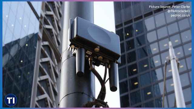
Conical Antennas Boost Vodafone Germany’s Tunnel Coverage

Mobile coverage in tunnels has always been one of the most difficult challenges for network operators. Concrete walls, restricted space and the constant movement of air caused by passing vehicles all interfere with signal stability. Vodafone Germany has now taken a major step forward in overcoming these barriers with the deployment of a new generation of conical antennas. Designed by Ericsson, these antennas are engineered specifically for tunnel environments and have been introduced in the 1,400 metre Arlinger Tunnel near Pforzheim.

The new solution is based on a conical multi-band antenna that combines wide frequency support with a form factor able to withstand tunnel-specific conditions. Traditional antennas in tunnels often struggle with vibrations and pressure changes that occur whenever trains or cars move large volumes of air. These effects can cause instability in reception and transmission performance. The conical design offers superior resistance to these forces. Its aerodynamic shape reduces the impact of airflow and turbulence, which results in more stable signal propagation and higher reliability.

Ericsson’s antenna, known as the Antenna 9011 1LM (KRE 101 2571/1), operates across the 617 to 4200 MHz range. This wide frequency coverage ensures compatibility with all major mobile technologies from legacy 2G through to 5G mid-band and even C-band. The antenna achieves a gain of around 10 dBi and uses cross polarisation to support advanced features such as MIMO. It has been tested under demanding tunnel conditions, including alternating pressure cycles that simulate the effect of trains passing at high speed. These design elements make it particularly suitable for deployment in both road and rail tunnels.

In the Arlinger Tunnel, five of these antennas have been installed. Together they provide seamless coverage along the full tunnel length, ensuring that drivers and passengers can stay connected without interruptions. For commuters this means fewer dropped calls and more consistent data performance, while for Vodafone it represents a significant step in eliminating dead spots in challenging locations. The project also demonstrates how antenna engineering is evolving to meet the requirements of complex environments.

Delivering mobile coverage in tunnels is more complicated than simply placing antennas inside the structure. In shorter tunnels, antennas positioned at the entrance and exit can often suffice. In longer tunnels, however, operators must deploy signal repeaters and distribute the signal along the length of the tunnel using multiple antennas. This requires the installation of cabling and associated equipment, usually during periods when tunnels are closed for maintenance. To avoid duplication, one operator typically provides the infrastructure and others connect their networks to it.

Germany has a particularly extensive tunnel network with more than 270 tunnels on federal highways, over 400 on district and urban roads, and 761 railway tunnels. Collectively these extend for more than 1,200 kilometres. The introduction of conical antennas marks a practical response to the specific difficulties these environments present. Vodafone has already announced that it intends to use the new antenna type in 20 further tunnel projects across the country.

From an infrastructure perspective, the Arlinger Tunnel deployment highlights a broader trend towards highly specialised antenna systems. Rather than adapting generic equipment, manufacturers such as Ericsson are now producing models tailored for environments where airflow, vibration and space constraints dominate. The Antenna 9011 1LM shows how much progress has been made. Its mechanical robustness, compact size and wideband capability make it a versatile component for future-proof tunnel deployments.

Vodafone Germany’s network already reaches more than 93 percent of the population with 5G and the addition of tunnel coverage strengthens this footprint. For the growing number of travellers who depend on uninterrupted connectivity, solutions like the conical antenna are not just a technical achievement but also a practical improvement to everyday digital life. They also underline the importance of collaboration between operators and equipment vendors in tackling some of the toughest remaining infrastructure gaps.

Related Posts

Tuesday, 29 July 2025

NGMN’s Common Language for Antennas Lays the Foundation for Future-Proof Infrastructure

Base station antennas are critical components of mobile networks, serving as the final link between radio systems and the air interface. Despite their importance, there has long been a lack of consistency in how antenna systems are specified, validated and integrated into networks. This inconsistency has led to inefficiencies in procurement, difficulties in multi-vendor environments, and challenges in scaling network performance. The latest publication from the NGMN Alliance, “Recommendations for Base Station Antennas”, aims to change this by introducing a harmonised framework for describing passive, active and hybrid antenna systems.

The updated document combines the previously separate guidance on passive and active antenna systems into a single, unified publication. Developed under the BASTA (Base Station Antenna) project, it defines a comprehensive set of electrical, mechanical and environmental parameters relevant to base station antennas. These include radiation characteristics such as gain, beamwidth, front-to-back ratio and sidelobe suppression, as well as practical aspects like dimensions, weight, connector type, wind load and ingress protection. For active antennas, it also defines parameters for beamforming capability, scanning range, traffic beam configuration and power control.

One of the key motivations behind the updated recommendations is the growing use of hybrid antenna systems. These combine passive elements, such as the antenna array and remote electrical tilt, with integrated active components like transceivers and digital beamforming units. Hybrid configurations are especially relevant in 5G networks, which rely on advanced techniques like massive MIMO and dynamic beam steering to deliver high capacity and spectral efficiency. However, deploying such systems at scale, particularly in disaggregated or Open RAN architectures, requires a standardised way to describe and compare antenna products from different vendors.

The NGMN publication addresses this need by introducing a structured methodology for presenting antenna parameters, including definitions, recommended test practices and digital exchange formats. Notably, it supports XML-based datasheets aligned with an agreed schema, enabling machine-readable processing of antenna data. This is particularly useful for operators seeking to automate parts of the network planning and procurement lifecycle, including performance comparison, site design and integration testing.

The framework also incorporates coordinate system conventions, including multiple spherical and Cartesian reference models, to provide flexibility in how antenna orientation and beam direction are described. This is essential for accurate modelling of antenna coverage and interference in radio planning tools. The document additionally covers Remote Electrical Tilt (RET) systems, including configuration management, software upgradeability and compliance with AISG protocols.

Importantly, the NGMN recommendations are designed to be implementation-agnostic. Rather than enforcing performance thresholds or mandating design practices, the focus is on standardising the language used to describe antenna characteristics. This approach ensures that innovative antenna designs, including those supporting new form factors or frequency bands, can still be accommodated as long as they conform to the descriptive framework.

A further advantage of the framework is its extensibility. While the current version focuses on antennas operating below 6 GHz, it is expected that future versions will include extensions for higher frequency bands and additional attributes such as energy consumption, carbon footprint and circularity. These sustainability metrics will become increasingly important as networks aim to reduce their environmental impact while delivering ever-higher performance.

The importance of this work becomes clear in the context of multi-vendor and disaggregated networks, where interoperability depends not only on open interfaces but also on consistent component descriptions. A shared vocabulary for base station antennas enables smoother integration, better lifecycle management and more effective use of network resources. It also reduces vendor lock-in and improves supply chain flexibility, which is especially valuable for operators pursuing Open RAN strategies.

As antenna systems continue to evolve, the ability to describe their behaviour and capabilities with precision will be vital. NGMN’s BASTA recommendations offer a practical and forward-looking solution, supporting both current deployment models and the transition toward future architectures such as 6G. By promoting transparency, repeatability and interoperability, this common language for antennas strengthens the foundation of mobile network infrastructure and contributes to a more efficient, open and sustainable ecosystem.

Related Posts

Thursday, 3 July 2025

Transforming Poles into 5G Sites with Alpha Fusion Streetworks Solutions

During a recent visit to Glasgow for the SCONDA project showcase, a collaborative initiative focused on advancing urban connectivity, I was struck by how far street-level network infrastructure has come in combining functionality with aesthetics. Among the most visually discreet and technically advanced deployments were those featuring Alpha Wireless' wraparound antennas. The AW4032 antenna stood out for its innovative design, enabling mid-pole mounting in a configuration that blended effortlessly with the urban environment while delivering high-performance 5G coverage. 

Live tests on attendees’ devices showed 5G download speeds reaching up to 720 Mbps, with improved coverage and congestion relief across city-centre locations. One attendee reported that the deployment achieved average 5G download speeds of 520 Mbps, while also reducing low-speed hours by 89% and reaching peaks of over 1 Gbps on small cells in a live dense environment.

Alpha Wireless has developed its Fusion Streetworks solutions with a clear understanding of the challenges faced by operators in urban areas. As network densification accelerates, especially with the move towards 5G standalone architectures, securing new street-level sites is proving increasingly difficult. The Fusion Streetworks platform responds to this by making better use of existing infrastructure such as lamp posts and streetlights. The AW4032 antenna, which forms the centrepiece of this platform, is designed to mount mid-pole without requiring sidearms or external hardware that would increase wind loading or visual impact. As it is an antenna-only product, the AW4032 pairs with external small cell radios, offering operators flexibility in radio selection.

The AW4032 combines compact form with support for advanced radio capabilities. It supports 16 ports across dual bands — 1695 to 2690 MHz and 3300 to 4200 MHz — and enables 4x4 MIMO, delivering strong signal quality and throughput. When ports in adjacent sectors are connected, the antenna produces a pseudo-omnidirectional pattern, providing seamless 360-degree coverage suitable for dense urban environments, hotspots and high-traffic venues. It is also highly adaptable. Operators can configure the ports to suit different patterns: back-to-back for focused directional coverage, or four-way for broader area coverage, all using the same hardware.

This modularity means the same unit can serve single or dual-operator deployments, with each operator connecting to a separate set of ports. This enables shared infrastructure without interference and lowers total cost of ownership. For instance, the dual-operator setup divides the 16 ports between two MNOs while still offering pseudo-omni performance, which is particularly useful in areas where zoning permissions limit the number of separate installations.

What makes the solution especially effective in public spaces is the attention to detail in concealment. The Fusion platform includes options for radio shrouds and integrated cabling management to maintain a neat appearance. This has been instrumental in speeding up approvals in areas traditionally sensitive to new telecoms infrastructure.

Alpha Wireless has already seen its Fusion Streetworks solutions rolled out as part of a 5G standalone deployment in central Birmingham. Working with Ontix and Virgin Media O2, these antennas have been deployed on existing poles in busy city locations, demonstrating how legacy infrastructure can be revitalised to meet the demands of next-generation connectivity.

From an infrastructure perspective, the AW4032 exemplifies how antenna technology is evolving to match the operational and regulatory pressures of modern small cell deployment. It simplifies rollout, minimises street clutter, and offers a level of future readiness that is essential for long-term network planning. For cities looking to accelerate their 5G ambitions without compromising on design, Alpha Wireless’ Fusion Streetworks platform offers a proven and practical approach.

Tuesday, 8 April 2025

Mobile Internet Setup for Vanlife: Infrastructure Insights from The Road Two Spoons

In today’s age of digital nomadism, mobile connectivity isn’t a luxury—it’s a necessity. For vanlifers like Jess and Marcus, better known as The Road Two Spoons, staying online while travelling full-time across Europe and Türkiye requires more than just a mobile hotspot. Their campervan serves as both home and office, meaning a robust and redundant internet setup is essential.

Their upgraded system offers a great case study into the infrastructure behind reliable van-based internet. It combines cellular and satellite connectivity with intelligent routing and efficient power use—demonstrating how mobile networking hardware can be optimised for life on the road.

The Core: A Multi-Path Internet Router

At the heart of the setup is the Teltonika RUTX50, a compact yet powerful 3G/4G/5G modem-router that supports multiple WAN inputs and advanced network management. Key features include:

  • Dual SIM support for redundancy (though only one slot is currently in use)
  • Auto-switching and load balancing capabilities
  • A low power draw suitable for off-grid living
  • 12V operation with physical on/off switching
  • Multiple antenna ports: 4 x SMA for 5G, 2 x ReSMA for Wi-Fi, and 1 x SMA for GPS
  • 5 x Gigabit Ethernet ports for flexible wired connections

The router integrates seamlessly with both a 5G antenna and a Starlink dish, offering connectivity even in the most remote regions.

Cellular Connectivity: Poynting Antenna Integration

For cellular signal reception, the van uses a Poynting MIMO-4-4 5G antenna. This external, roof-mounted unit connects directly to the RUTX50 to ensure strong signal acquisition, especially in fringe coverage areas.

This antenna enhances the performance of their ConnectPls Europe unlimited data SIM, providing primary connectivity when Starlink is unavailable or switched off. The setup allows automatic failover between cellular and satellite internet sources, keeping downtime to a minimum.

Satellite Support: Starlink Gen3 + Starvmount

Mounted securely on the van roof is a Starlink Gen3 (V4) dish, using the Starvmount DishyMultiMount. This combination ensures:

  • Flat, in-motion satellite connectivity via Starlink Roam
  • Fixed mounting at an optimal 8° angle, aiding both signal quality and weather resilience
  • Improved mechanical security over Starlink’s original mobility mount

Thanks to Starlink’s global coverage and low-Earth orbit satellite constellation, the couple can achieve 200+ Mbps speeds in locations where even sending a text would otherwise be impossible.

Power Considerations: 12V Starlink Conversion

To avoid reliance on inverters and 230V AC power, the Starlink system runs directly off the van’s 12V power system using a Starvmount Dishy NoAC DC power supply. This device:

  • Accepts a wide input voltage (9–36V), suitable for 12V or 24V installations
  • Offers plug-and-play integration between the Starlink dish and the RUTX50
  • Eliminates the need for Starlink’s original AC-powered router
  • Emits a minor static noise under load, so is ideally installed in a cupboard or enclosed space

A dedicated 12V switch allows the system to be powered down when not in use, contributing to overall energy efficiency.

Cabling and Waterproofing: Roof-Grade Sealing

Cables for both Starlink and the Poynting antenna are routed through the van’s roof using Scanstrut DS-H-MULTI-BLK cable seals. These seals are:

  • IP68-rated for waterproofing
  • UV-stable to withstand prolonged sun exposure
  • Trusted for roof penetrations in marine and automotive applications

This careful attention to weatherproofing ensures long-term reliability of the system, even in extreme environments.

One Wi-Fi Access Point, Seamless Switching

Because both Starlink and cellular data feed into the same RUTX50 router, the van operates a single internal Wi-Fi access point. The router automatically prioritises the Starlink connection when available, and falls back to the SIM card with minimal delay when Starlink is powered off.

This means no manual reconfiguration is required, simplifying the digital experience onboard and allowing Jess and Marcus to focus on their work, travel, and content creation.

Final Thoughts: Engineering Freedom on Four Wheels

What makes this campervan internet setup impressive is not just the performance, but the thoughtful integration of multiple technologies: 5G, satellite broadband, power management, and rugged installation. By combining a modular approach with careful hardware selection, The Road Two Spoons have created a high-reliability infrastructure that could easily be adapted to off-grid cabins, remote workstations, or mobile command vehicles.

As connectivity becomes more critical in all forms of modern living, this vanlife case study offers valuable insights into how telecom infrastructure can be effectively deployed outside traditional settings—bringing reliable broadband to wherever the road leads.

Watch the Setup in Action 🎥

Here’s a short video from The Road Two Spoons walking through their full campervan internet setup—from antennas to modems and Starlink on 12V:

Related Posts

Tuesday, 14 January 2025

Decoding Starlink: The Technology Behind the Revolution

Starlink has been a regular feature on our blog. The race to provide global connectivity has seen remarkable innovation, and Starlink, SpaceX's satellite internet service, has been at the forefront. By utilising a network of low Earth orbit (LEO) satellites, Starlink promises faster speeds and reduced latency compared to traditional satellite internet. But what exactly sets Starlink apart? Let’s delve into the technical marvels behind this ground-breaking system.

Traditional broadcast satellites operate in geostationary orbits, approximately 35,000 kilometres above Earth. In contrast, Starlink's LEO satellites, orbiting at altitudes of around 550 kilometres, drastically reduce the distance signals travel. This significantly enhances performance and reduces latency, forming the foundation of Starlink’s technological advantage.

With Starlink internet, data is continuously exchanged between a ground dish and a Starlink satellite zooming across the sky at an incredible 27,000 km/h. How can the dish and satellite maintain a continuous connection? And how is data transmitted so efficiently? The video below delves deeply into the workings of the ground dish and satellites, revealing how a beam of data is formed, how it is swept across the sky, and what precisely is in that beam enabling incredibly fast internet speeds. This is a remarkable feat of technology and engineering!

Inside the Starlink Dish: Dishy McFlatface

At the heart of the Starlink system is its ground terminal, affectionately known as Dishy McFlatface. This device features an aperture-coupled patch antenna, a sophisticated design that allows it to efficiently emit and receive electromagnetic waves. Unlike traditional parabolic dishes, Dishy is compact, sleek, and meticulously optimised for Starlink’s specific needs.

How Does Dishy Work?

Dishy’s ability to send and receive data hinges on two critical technologies: beamforming and phased array beam steering.

  • Beamforming enables the dish to focus its electromagnetic waves into a directed beam, efficiently reaching Starlink satellites in orbit.
  • Phased Array Beam Steering introduces dynamism, allowing the beam to move across the sky by electronically adjusting the phase of signals emitted from various antenna elements. This agility is essential for maintaining a seamless connection with rapidly moving LEO satellites.

A Look at Signal Transmission

Once a beam is formed and directed, Dishy employs advanced modulation techniques, such as 64QAM (Quadrature Amplitude Modulation), to transmit data. This method combines amplitude and phase variations, maximising data throughput—a vital requirement for high-speed internet services.

Scaling Down: Electromagnetic Waves and Dishy’s Dimensions

Despite its advanced functionality, Dishy remains surprisingly compact. This miniaturisation is achieved by leveraging the properties of electromagnetic waves and employing innovative design principles, as outlined in Starlink’s patents.

The Bigger Picture

Starlink’s phased array technology represents a monumental leap in satellite communications, with implications extending beyond internet services. Its ability to dynamically steer beams has the potential to revolutionise fields such as autonomous vehicles, IoT, and remote sensing.

Conclusion

Starlink isn’t merely about providing internet access; it’s about redefining the very concept of connectivity. Through ground-breaking innovations in satellite placement, ground terminal design, and signal processing, Starlink sets a new benchmark for telecom infrastructure.

Video Contents

All the above is explained in a fantastic manner in the video embedded below. The video’s table of contents with timestamps for easy navigation as follows:

  • 00:00 - Intro to Starlink
  • 01:00 - Overview of Exploring Starlink
  • 01:46 - Difference between Starlink and Broadcast Satellites
  • 03:28 - Parts Inside a Dishy McFlatface
  • 05:06 - How Does an Aperture-Coupled Patch Antenna Work?
  • 09:13 - Electromagnetic Wave Emission
  • 12:45 - Forming a Beam that Reaches Space: Beamforming
  • 15:22 - Brilliant
  • 16:52 - Steering a Beam to Sweep Across the Sky
  • 18:54 - Starlink: Phased Array Beam Steering
  • 21:11 - Notes on Phased Array Beam Steering
  • 22:24 - Sending Data in a Beam to the Starlink Satellite
  • 23:27 - Inner Workings of 64QAM
  • 26:02 - Actual Size of Starlink Dishy & Electromagnetic Waves
  • 26:55 - Images from the Starlink Patent
  • 27:49 - Outro

Related Posts: 

Tuesday, 17 September 2024

High-Speed FWA Using mmWave With the Help of Li-Fi

On a regular basis I keep reading about how Fixed Wireless Access (FWA) continues to gain ground at the expense of cable operators, especially in the USA (see articles by Ookla, OpenSignal). One of the challenges with FWA is the need to (generally) install external antennas, especially when higher frequencies like mmWaves is involved.

One of the approach would be to use transparent antennas that I have explained here. This would be difficult for residential consumers. The other approach, championed by pureLiFi is to use Light Based Communications to let the signal pass from outside to inside. Both these approaches were my wow moments at MWC 2024.

TelecomTV has a nice write-up on the pureLiFi/Solace solution from the conference here. Quoting from that:

This week, pureLiFi announced the LINXC Bridge, a self-installable double limpet that attaches itself to both sides of a window (see picture, above). 

“The idea is to help the signal get through glass,” explained pureLiFi CEO, Alistair Banham. The device transmits an optical version of the incoming radio signal through the glass window so the data can then be distributed to a router or other device once inside the room.

According to Banham, “getting outside signals in” has become ever more difficult as radio technologies have climbed the frequency range and adopted complex encodings, such as orthogonal frequency division multiplexing (OFDM), while the materials used to construct buildings have become less  permeable to radio signals. This is a looming problem, he says, because telcos will increasingly rely on millimetre wave (mmWave) fixed 5G radio links to extend broadband services, especially to those hard-to-reach homes and businesses in remote locations, and mmWave doesn’t like walls or windows.

The pureLiFi LINXC Bridge, developed in partnership with Canadian company Solace Power, is designed to overcome some of those problems. “A top priority is the avoidance of truck roll, so a key attraction for our telco customers is the system’s ease of installation – there’s no requirement to for an outside antenna or hole-boring through the side of the customer’s building, as the LINXC is designed to be self-installed, which eliminates installation costs and shortens the time to market for telco-delivered wireless broadband,” said Banham.

But the real Li-Fi breakthrough came about halfway through 2023 when the IEEE (Institute of Electrical and Electronics Engineers) took the wraps off 802.11bb, the optical variant of the Wi-Fi standard and, as a result, Li-Fi and Wi-Fi should be able to interwork within a customer’s premises. 

“Last year,” Banham explained, “we developed the light antenna so a Wi-Fi network can see it as just another antenna, so now we have full interoperability and that means we can demonstrate a complete ecosystem so that customers can see, touch, feel and understand its benefits.”

Perhaps the biggest benefit, and most attractive niche for Li-Fi, is within so-called radio sensitive environments which, thanks to the interoperability with Wi-Fi,  will enable it to selectively reach and connect things like critical medical equipment, for instance (a large and growing application area).

The new mmWave bridge product isn’t pureLiFi’s only offering –  there’s SkyLite, a “whole-room Li-Fi access point” and the Cube, described as a simple, secure working from home, gaming, streaming and on-the-move connectivity device.  

Banham says the ambition doesn’t stop there, as the company has plans to have Li-Fi “augment and extend other wireless and wireless technologies, ushering in a new era of bandwidth, speed and reliable communications."

The press release from Solace Power also includes the video of the solution and is available here.

Related Posts

Friday, 25 March 2022

Taoglas Advanced Antennas and RF Components

Taoglas is a leading provider of advanced technology for a smarter world. Focused on best-in-class, high-performance antenna and RF design with advanced positioning, imaging, audio and artificial intelligence technologies, Taoglas has unique expertise in integrating and commercializing highly complex technology solutions. 

At the Mobile World Congress 2022, we caught up with Baha Badran, Global Head of Engineering at Taoglas to tell us about the different types of antennas and what they are used for. Baha didn't disappoint us and gave us a whirlwind tour of all the antennas on the display at their booth. The video is embedded below.

To learn more about Taoglas, visit their website here.

Related Posts

Friday, 17 December 2021

Demos from Ericsson's Radio Tech Day 2021

Ericsson's Radio Tech Day is a cyclical meeting intended for the telecommunications industry and technical staff of operators in Poland. Engineers share projects, describe best practices and learn from each other's experience. During the conference, the latest solutions in the field of radio and core technology, both in the field of software and hardware, as well as the achievements of start-ups cooperating with the company, are presented.

The following video is from the recent event held last month:

Related Posts

Monday, 29 November 2021

Huawei MetaAAU Promises Improvement in 5G Network Performance and Energy Efficiency


Huawei's latest Active Antenna Unit, MetaAAU is billed as having loads of improvement and potential. A sponsored article on Light Reading says:

Speaking at the recent Mobile Broadband Forum event in Dubai, Yang Chaobin, president of Huawei Wireless Solution, flagged numerous technology innovations and advances that take the traditional AAU (active antenna unit) found in Massive MIMO onto another level.

MetaAAU, developed by Huawei, incorporates ELAA (extreme large antenna array) technology supporting 384 antenna elements. It’s double the number of a traditional AAU.

“By introducing 384 antennas in the AAU, coverage can be improved by 3dB on both the downlink and the uplink, and the user experience can also be improved by 30%,” said Chaobin, “Energy savings of 30% can also be achieved.”

The Official Huawei press release points out: 

Released in October this year, Huawei's 64T64R MetaAAU is the ideal solution to improve both network performance and energy efficiency using innovative hardware and software. For hardware, MetaAAU introduces the extremely large antenna array (ELAA) which enables 384 antenna elements, double that of a conventional AAU (192). ELAA is combined with ultra-light integrated array and signal direct injection feeding (SDIF) to improve both coverage and integration. For software, MetaAAU utilizes the Adaptive High Resolution (AHR) Turbo algorithm to enable precise, dynamic, and targeted beamforming, significantly improving user experience and cell capacity. This hardware/software combo marks a new breakthrough in Massive MIMO coverage and energy efficiency.

In comparison with conventional 64T64R AAU and 32T32R AAU, MetaAAU improves coverage by 3 dB and 6 dB and user experience metrics by 30% and 60%, respectively. For example, in one of its flagship projects — 5G Capital that brings 5G to every corner of Beijing — China Unicom Beijing is using MetaAAU to add 30% in both uplink and downlink coverage along with 25% better experience among cell edge users.

MetaAAU is also a powerful energy-saving tool. It allows base stations to achieve the same level of coverage for cell edge users but with a lower transmit power, reducing energy consumption by approximately 30% over conventional AAUs. This has also been tested in the 5G Capital project.

With its advantages in energy efficiency and coverage, MetaAAU is slated for success. Going green is now a global objective — for example, 26 CEOs of European ICT companies have committed to combat climate change with the European Green Digital Coalition (EGDC). At the same time, 5G network coverage requirements will only continue to grow, rolling out 5G in rural and urban, outdoor and indoor contexts. Leading next-gen ICTs will be key in delivering on both demands; and Huawei's MetaAAU stands to be part of the innovation portfolio.

Going back to the Light Reading article:

If traditional materials found in antenna dipoles were applied to ELAA, for example, the weight would drastically increase, making it more difficult and expensive to install on cell sites.

Moreover, without miniaturized filters, ELAA dimensions necessarily become much bulkier compared with traditional massive MIMO antenna. Cell-site space is already constrained and operators don’t want to go through the lengthy process of gaining permission to occupy more tower space, which, in turn, increases maintenance costs.

Another challenge is that antenna elements in a traditional RF feeding network architecture are normally connected by cables, which are an inefficient way to transfer signals. If the antenna array doubles to 384 elements, the length of cable – along with the extent of inefficiencies – increases.

Through a series of hardware innovations, however, MetaAAU makes the transition to ELAA feasible and attractive. Using ultra-lite metamaterials, MetaAAU is around the same weight as the original 64T64R massive MIMO AAU. Adoption of Huawei’s compact wave filter also means MetaAAU dimensions do not require more space.

To address hardware energy inefficiencies, Huawei has adopted SDIF (signal direct injection feeding) technology. SDIF replaces cables with a more energy-efficient metal-type structure.

Aside from hardware innovation, MetaAAU introduces an adaptive high-resolution beamforming algorithm, dubbed AHR (Adaptive High Resolution) Turbo. It has various features, which, when combined, not only reduces wasted radiation energy but also cuts down on ‘noise’ that can degrade network performance.

Among the benefits of AHR Turbo is that it enables MetaAAU to generate extremely narrow beams that can precisely latch onto user equipment, as well as boost air-interface efficiencies by allowing beams to dynamically adapt to radio channel

Here is an official video of MetaAAU

Mobile World Live also has an infographic, which is the source for the image on the top. It's available here.

Related Posts

Monday, 15 November 2021

Will Distributed FD-MIMO be next big MIMO Enhancement?

We have looked at MIMO quite a few times in this blog. Back in February we looked at some of the advancements that Samsung and Ericsson had been showing here.

Last year, in a blog post, Samsung talked about Distributed Full Dimension MIMO (FD-MIMO). The key points were:

Around that time, the concept of Massive MIMO was proposed in academic papers. These papers proposed the idea of making the signal dimension at the base station much bigger by using a massive number of antennas such that all inter and intra-cell interference asymptotically go to zero. MU-MIMO performance would be improved significantly with a much lower interference level, therefore leading to capacity gain. It looked promising, but no one knew how to bring it to reality, since arranging 10s or 100s of antenna elements in the conventional way (i.e., in the horizontal plane) would lead to a base station that is longer than a bus, so obviously it was not going to work in a real deployment.  

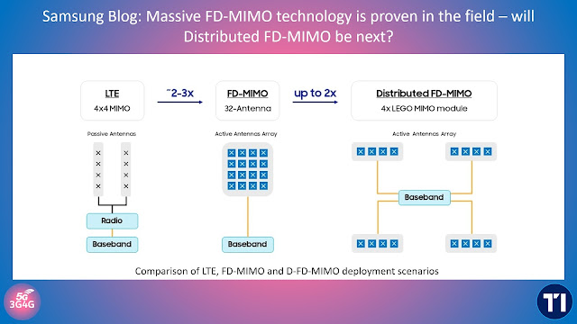
An important breakthrough came when engineers at Samsung noticed that a concept called Active Antenna Systems (AAS), could be exploited to organize 64 or 128 antennas into a 2D active antenna array that is similar in size with a conventional 4-TX system as shown in the middle portion of Figure 1. Such a system is called a Full Dimension MIMO (FD-MIMO) system. Initial evaluation of the FD-MIMO system coupled with high-order MU-MIMO showed a capacity gain by a factor of 3-4 times for a 64 or 128-TX FD-MIMO compared to a 2-TX LTE system, as was summarized in a 2012 Globecom paper , “Fulfilling the promise of massive MIMO with 2D active antenna array”, and later in a 2013 IEEE magazine paper , “Full-dimension MIMO (FD-MIMO) for next generation cellular technology”. 

Samsung has been actively leading the FD-MIMO standardization process in 3GPP from the beginning, including the 3D channel model study in 2012 that paved the way for subsequent system design, the 4G LTE version of elevation beamforming and the FD-MIMO work from 2014, and more recently the 5G NR-MIMO version of FD-MIMO. Samsung has also been a leader in prototyping and testing the feasibility of the technology and was the first to demonstrate an FD-MIMO system supporting 12 simultaneous MU-MIMO users achieving a record aggregate capacity of > 20 bps/Hz in early 2015. These feasibility study result was later published in a 2017 IEEE JSAC paper , “Full Dimension MIMO (FD-MIMO): demonstrating commercial feasibility”.

Initial system level simulations show that the D-FD-MIMO system achieves up to 2 times cell average throughput gain compared to the FD-MIMO system, lifting both cell capacity as well as average user throughput. Such a cellular system can be flexibly deployed to “blanket” a given geographical area and provide better service for both outdoor and indoor users. 

We have developed a hardware prototype and performed field test to verify the feasibility and the performance gain of the D-FD-MIMO system. In the field test, 3 distributed LEGO MIMO RFUs and 7 UE emulators were used. When the number of active RFUs increased from one to three, the overall throughput improved by about 4 times.

A significant amount of work needs to be done before we can accurately quantify the benefits of the D-FD-MIMO technology, but these initial results are certainly promising and show a great potential for this new breakthrough of the MIMO technology.

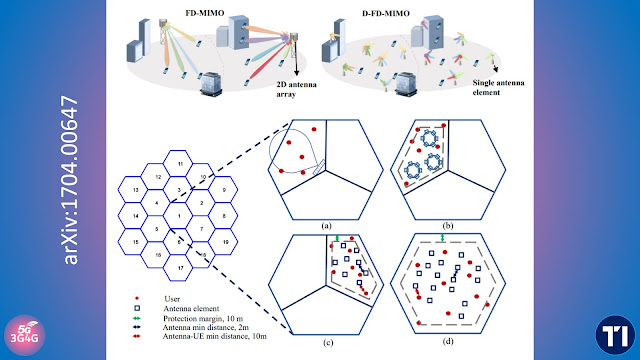
Back in 2017, Samsung researchers also wrote a paper on this topic, Distributed FD-MIMO: Cellular Evolution for 5G and Beyond, which is available on arXiv here. Quoting from the paper:

Distributed Full Dimension MIMO (D-FD-MIMO) is an evolution of FD-MIMO. A D-FD-MIMO network assumes a cellular structure, where a cell is served by one BS and each BS is connected with a large number of antenna elements, of which individual elements are spatially distributed in the cell. One or more antenna elements are equipped with a digital port, and the signals transmitted and received from all the antenna elements within one cell are jointly processed to perform high order MU-MIMO operation.

Such a cellular system can be deployed outdoors in a city-wide area to provide service to both outdoor and indoor users. It can also be deployed inside the building to serve indoor users only. It is also suitable for providing service in a highly populated area, such as stadiums, shopping centers and airports, where a large number of the users are densely located.

Concepts relating to D-FD-MIMO includes distributed massive MIMO, CoMP (a.k.a. network MIMO) and distributed antenna systems (DAS). Distributed massive MIMO treats the entire network as one cell, featuring an enormous number of access points distributed over a large area, jointly serving all the users. pCell by Artemis can be seen as an implementation of the distributed massive MIMO albeit with a smaller scale in terms of the number of antennas. CoMP relies on the coordination among a few transmission points from the same or different sites to enhance User Equipment (UE) experience at the cell edge. DAS is initially proposed to improve coverage in an indoor cellular communication system, and is sometimes adopted in outdoor scenarios as well. One configuration for outdoor deployment is to have a few antenna arrays distributed throughout the cell to perform MIMO operations. Another DAS configuration deploys a number of individual antenna elements in a distributed manner in each cell of the network, which is similar to the D-FD-MIMO setting. Different from our system-level simulation approach, the analysis theoretically derives the asymptotic sum capacity when the numbers of UE and antennas in each cell both approach infinity with their ratio fixed, and assuming perfect uplink power control.

You can get the PDF of the paper here.

We have written about the Cell-Free Massive MIMO here and here. One of the realizations of D-FD-MIMO is as shown in Ericsson Radio Stripes. 

Researchers on this topic may also be interested in watching Wireless Future Podcast episode 13 on Distributed and Cell-Free Massive MIMO (embedded below). The description says:

In this episode, Erik G. Larsson and Emil Björnson discuss how one can create cell-free networks consisting of distributed massive MIMO arrays. The vision is that each user will be surrounded by small access points that cooperate to provide uniformly high service quality. The conversation covers the key benefits, how the network architecture can be evolved to support the new technology, and what the main research challenges are.

The description also contains some links and the discussion is also interesting to follow. You can jump on to the video directly here.

Related Posts:

Sunday, 10 October 2021

Multi-sectorised sites and Small Cells help O2 UK handle Capacity in Busy Areas

Radio planning becomes essential in dense urban areas where operators don't only have to serve the highly mobile users but also slow moving pedestrians and users indoors. One some location in London, UK, is O2 UK's highest capacity Nokia site with six-sector low-band LTE in 800 and 900MHz in addition to high-band 4T4R L18/L21, 8T8R L23 as well as standard n78 8T8R 5G.

The site also features numerous high-end Commscope antennas with dual-beam panels that are needed to create six-sector LTE 800 and 900 MHz and then 24 port antennas that carry all the other including 8T8R 2300 MHz, 1800 MHz, 2100 MHz as well as n78 8T8R.

In addition, O2 has multitude of Nokia Small cells sprinkled across the City of London. While these come in all different shape and configurations. In many locations there are ones with directional antennas while there are others with omni-directional antennas as well.

The small cells are located on their own poles, rather than lamp posts and many of these also feature Wi-Fi access points as additional means to alleviate the capacity crunch. In fact they can also be mounted on-top of phone boxes, shops, side of buildings, etc. 

If this is an area of interest and you enjoyed reading the post above, you will no doubt enjoy watching this short video from Peter Clarke who has a great collection of infrastructure from UK and Ireland on his website here. Video as follows:

Related Posts

Friday, 13 August 2021

MatSing's High-Capacity RF Lens Antennas

We have looked at the Lens antennas in a few blog posts indirectly. The most recent being Facebook's SuperCell while others being Altaeros’ Autonomous Tethered Aerial Cell Tower and Verizon's U.S. Bank Stadium

In a recent press release, MatSing announced that it has been selected by the Dallas Cowboys and its network provider AT&T, along with ExteNet Systems, to provide mobile capacity antenna coverage for AT&T Stadium for the upcoming NFL season. Selected extract as follows:

These antenna upgrades will further enhance the exceptional experience provided by AT&T for fans in AT&T Stadium. This deployment follows a test run with reduced crowds during last season. This selection was made due to the capacity of MatSing technology to work with the AT&T systems at the stadium.

Following the installation of 20 MatSing lens antenna by ExteNet covering the Stadium’s entire seating bowl and field with 4G and 5G broadband mobile coverage, the fans and patrons will now experience never seen before performance with their smart devices in the stadium.

“With data demands of cell phones continuing to grow exponentially, driven by new apps and technology, our legacy DAS infrastructure could not keep up with those demands,” explained Cowboys CIO Matthew Messick. “AT&T introduced us to MatSing’s antenna technology, and immediately knew their technology would give us the necessary capabilities with room to grow.”

“Operating the largest indoor DAS network in the United States at AT&T Stadium provides us a unique opportunity to enable the best possible fan experience at one of the NFL’s most iconic venues,” added Rich Coyle, President & Interim CEO, ExteNet Systems. “We thank the Dallas Cowboys for trusting us with this opportunity, and MatSing for providing the clear winning technology for our mobile broadband needs.”

MatSing's spherical lens antennas are based on a unique patented technology that allows a single antenna to provide up to 48 high-capacity coverage sectors, replacing up to 48 traditional antennas with a single lens. Unlike other current solutions, like under-seat antennas, the MatSing lens antennas installed in the roofing structure typically have a clear line-of-sight path to potential users. This significantly reduces the number of antenna locations, as lens antennas can also reach farther than traditional antennas, providing better AT&T coverage and less interference at a lower cost and complexity for the team.

“A smoother Internet experience able to handle modern-day demands of streaming and social media sharing awaits Cowboys fans when they return to AT&T stadium,” added Michael Matytsine, MatSing co-founder and EVP of Operations. “Even when the stadium is at full capacity, lens antennas will provide a smoother data experience with fewer interruptions for fans who have embraced streaming and sharing as an intrinsic part of their stadium experience.”

AT&T, ExteNet and MatSing will continue to work with the Cowboys to maintain and test the lens equipment ahead of the season, ensuring its readiness for wider use by fans in AT&T Stadium.

MatSing lens antennas have also been present in the inauguration's of US presidents. The one from this year is in the Tweet above while the one from last election in 2016 is available here.

Related Posts:

Friday, 6 August 2021

Panorama's ESN Antennas

It feels like last year when I was involved in testing some emergency networks but it was a long while back.

Believe it or not, your mobile network is only as good as the antennas. How often have I come across networks that try and add some cheaper antennas to cut down the costs but the loss of coverage, especially on the edges is a far bigger loss than saving some money on the antennas. 

The UK's Emergency Services Network (ESN) is moving along nicely, though far slower than most people expected it to. One of the important pieces of the puzzle is different types of antennas that are needed on the blue light vehicles. The image on the top nicely summarises these antennas and a brochure with details is available from Panorama here. In fact you can check out all different types of antennas here.

The following videos provide an idea on how these antennas look and work

Do check out other posts below related to ESN on our blogs.

Related Posts:

Thursday, 1 July 2021

Bringing Connectivity to Underground Rail Network

It's always been a challenge to bring mobile connectivity to commuters in the underground rail network. The same challenges extend to mines and other facilities under the ground. One solution that has been widely adopted is the use of leaky feeders as antennas.

This solution is also used to compliment the existing terrestrial network in case of tunnels. We made a small tutorial looking at this from metro point of view but the same solution is applicable in many different scenarios. 

The video and slides are embedded below


5G presents a small challenge for this as it is tricky to go beyond 4T4R easily. Each T/R requires a leaky feeder which makes it expensive as well as challenging in other scenarios.

Related Posts

Saturday, 26 June 2021

Vodafone UK's 5G Infrastructure


Ker Anderson, Head of Radio and Performance, Vodafone UK did an IET presentation looking at Vodafone's infrastructure, especially 5G infrastructure. The video from that has been publicly shared so it is embedded below.

Related Posts:

Friday, 18 June 2021

Cell-Site Construction And Evolution Strategies


We all agree that cell sites are complex beasts. The diagram above shows in a simple way all the tasks that may be necessary for cell site deployment. Late last year, ABI Research produced a whitepaper on "Global Cell-Site Construction And Evolution Strategies" that they made freely available here. Quoting the executive summary below:

5G networks are being rapidly deployed around the world with many of these networks working in parallel to existing legacy cellular technologies, such as 2G/3G and 4G, to provide higher data connections of 10X more throughput than 4G. 5G networks typically use high-frequency spectral resources (C-band and mmWave) and, according to the International Mobile Telecommunications 2020 (IMT-2020), the downlink and uplink peak data rate of a 5G network should be 20 Gigabits per Second (Gbps) and 10 Gbps, respectively, with downlink and uplink peak cell spectral efficiency of 30 bit/Second (s)/Hertz (Hz) and 15 bit/s/Hz, respectively. The use of higher frequency bands, which suffer from higher penetration loss and the continuous increase in requested data rates for end users, dictate the necessity of higher network availability and network capacity, which could be achieved through additional spectral resources and network densification. Many MNOs have already bought at auction spectrum for 5G deployment, but the network capacity can be maximized through network densification. Thus, the acquisition of cell site assets is critical for Mobile Network Operators (MNOs) for the effective performance of 5G networks.

These network requirements have brought huge challenges to MNOs, local governments, vendors, and System Integrators (SI), as some of those challenges are well-known unsolved issues evidenced by the deployment of legacy generations of cellular technologies and have become even more relevant now with the advent of 5G and the expected large-scale cell site densification.

These challenges range from the high cost associated with deploying network infrastructure at street level, to complex approval processes from local government, including lengthy and expensive site acquisition processes; lack of power availability; limited backhaul availability; lengthy planning application processes for street works or build works; limited space availability on premises and within street furniture; size and flexibility of existing cellular equipment that can fit the different rollout scenarios (e.g., smaller antennas to fit within wall-mounted small cell enclosures); lack of availability of underground space for the deployment of a new chamber and ducts; decluttering policies from local governments that can largely impact the deployment of 5G networks; and increasing tenancy fees for additional 5G equipment and increased power supply.

In response to this situation, there is some pressure on telecom equipment vendors to come forward with solutions that suit each rollout scenario. Improved physical features, such as smaller form factor antennas similar to the Wi-Fi Access Points (APs), lighter-weight and smaller Massive Multiple Input, Multiple Output (mMIMO) antennas, and an innovative variety of vendor equipment, backhaul, and reduced power consumption solutions will help MNOs address these challenges and stay ahead of the competition.

Finally, unlike previous generations of cellular technologies, policymakers, urban planners, and local governments have an important role to play, providing more flexible legislation that enable the rollout of network infrastructure at a faster speed by providing clear guidelines for easy access to the assets for the deployment of cellular infrastructure.

While many topics have been covered in the whitepaper, one of the issues I have closely experiences is the insufficient power for the new upgrades. Again, quoting from the whitepaper:

ENERGY

When deploying a cell site, the power requirement can typically be categorized as: 1) static power consumption, which is associated with the support system of a base station, and 2) dynamic power consumption, which is associated with the data traffic load. For a cell site, the amount of energy consumption varies depending on the amount of equipment and the number of frequency bands supported. Optimizing energy consumption can help operators lower their OPEX and achieve environmental goals.

CHALLENGES

Insufficient DC power capacity. Energy consumption is expected to increase with 5G deployments. New frequency bands and an increased number of equipment contribute to the this. Research on developed markets indicates that the maximum power consumption of a typical site supporting five bands could exceed 10 Kilowatts (kW). However, the reality is that about 30% of macrocell sites do not have a power supply that could support such power requirements. The common solution for energy expansion is adding more rectifiers or more energy cabinets. However, the equipment room or cabinet do not always have sufficient space for additional equipment. To cater to the increasing demand for energy, operators need to either find solutions that improve the existing equipment’s efficiency or construct new cabinets at sites. However, newly constructed cabinets also entail increased civil work and rental costs for operators.

Grid reconstruction. Grid power for the existing sites may be insufficient, especially due to the increase in power consumption with a 5G deployment. Such sites need grid modernization, which can be expensive and can greatly slow down the pace of a 5G deployment. Due to the process and construction requirements, the time to modernize the grid could be up to a year for each site.

Insufficient power backup. Operators need to meet the strict five nines or high availability of services. Ensuring business continuity is crucial for any operator. In times of prolonged bad weather or a power outage, grid and solar energy might not be available to power the cell site. Energy storage systems with lead-acid or lithium-ion batteries, for example, are required to mitigate the risk of a power outage. Most existing networks are still using lead-acid batteries, while the low-energy density, heavy weight, and big volume of a lead-acid battery make it difficult to do an expansion when deploying 5G.

High electricity cost. Another key challenge for operators is how to optimize energy efficiency, translating into good investments by operators. Relying solely on the electric grid could result in high energy expenditure, and the need to consider multiple energy resources. Traffic usage is also not constant throughout the day and varies depending on the location (e.g., city centers versus suburbs). How operators can manage the energy system intelligently and efficiently to reduce unnecessary waste becomes a core consideration.

Given the rapid development of 5G technology and an increasing host of service applications, computing is getting closer to users, with communication technologies and information technologies evolving toward converged Information and Communications Technology (ICT) architecture at an ever-faster pace. The increasing applications and computing required at the edge means that the power supply demand is expected to increase. Therefore, it is necessary to consider the amount of Alternating Current (AC)/Direct Current (DC) power supply needed at the cell site, as well as the number of equipment rooms that are required.

The paper goes on to describe the solutions. You can download the paper here.

If you have a favourite cell site issue do let us know in the comments.

Related Posts: