Showing posts with label Infrastructure. Show all posts

Tuesday, 8 April 2025

Mobile Internet Setup for Vanlife: Infrastructure Insights from The Road Two Spoons

In today’s age of digital nomadism, mobile connectivity isn’t a luxury—it’s a necessity. For vanlifers like Jess and Marcus, better known as The Road Two Spoons, staying online while travelling full-time across Europe and Türkiye requires more than just a mobile hotspot. Their campervan serves as both home and office, meaning a robust and redundant internet setup is essential.

Their upgraded system offers a great case study into the infrastructure behind reliable van-based internet. It combines cellular and satellite connectivity with intelligent routing and efficient power use—demonstrating how mobile networking hardware can be optimised for life on the road.

The Core: A Multi-Path Internet Router

At the heart of the setup is the Teltonika RUTX50, a compact yet powerful 3G/4G/5G modem-router that supports multiple WAN inputs and advanced network management. Key features include:

  • Dual SIM support for redundancy (though only one slot is currently in use)
  • Auto-switching and load balancing capabilities
  • A low power draw suitable for off-grid living
  • 12V operation with physical on/off switching
  • Multiple antenna ports: 4 x SMA for 5G, 2 x ReSMA for Wi-Fi, and 1 x SMA for GPS
  • 5 x Gigabit Ethernet ports for flexible wired connections

The router integrates seamlessly with both a 5G antenna and a Starlink dish, offering connectivity even in the most remote regions.

Cellular Connectivity: Poynting Antenna Integration

For cellular signal reception, the van uses a Poynting MIMO-4-4 5G antenna. This external, roof-mounted unit connects directly to the RUTX50 to ensure strong signal acquisition, especially in fringe coverage areas.

This antenna enhances the performance of their ConnectPls Europe unlimited data SIM, providing primary connectivity when Starlink is unavailable or switched off. The setup allows automatic failover between cellular and satellite internet sources, keeping downtime to a minimum.

Satellite Support: Starlink Gen3 + Starvmount

Mounted securely on the van roof is a Starlink Gen3 (V4) dish, using the Starvmount DishyMultiMount. This combination ensures:

  • Flat, in-motion satellite connectivity via Starlink Roam
  • Fixed mounting at an optimal 8° angle, aiding both signal quality and weather resilience
  • Improved mechanical security over Starlink’s original mobility mount

Thanks to Starlink’s global coverage and low-Earth orbit satellite constellation, the couple can achieve 200+ Mbps speeds in locations where even sending a text would otherwise be impossible.

Power Considerations: 12V Starlink Conversion

To avoid reliance on inverters and 230V AC power, the Starlink system runs directly off the van’s 12V power system using a Starvmount Dishy NoAC DC power supply. This device:

  • Accepts a wide input voltage (9–36V), suitable for 12V or 24V installations
  • Offers plug-and-play integration between the Starlink dish and the RUTX50
  • Eliminates the need for Starlink’s original AC-powered router
  • Emits a minor static noise under load, so is ideally installed in a cupboard or enclosed space

A dedicated 12V switch allows the system to be powered down when not in use, contributing to overall energy efficiency.

Cabling and Waterproofing: Roof-Grade Sealing

Cables for both Starlink and the Poynting antenna are routed through the van’s roof using Scanstrut DS-H-MULTI-BLK cable seals. These seals are:

  • IP68-rated for waterproofing
  • UV-stable to withstand prolonged sun exposure
  • Trusted for roof penetrations in marine and automotive applications

This careful attention to weatherproofing ensures long-term reliability of the system, even in extreme environments.

One Wi-Fi Access Point, Seamless Switching

Because both Starlink and cellular data feed into the same RUTX50 router, the van operates a single internal Wi-Fi access point. The router automatically prioritises the Starlink connection when available, and falls back to the SIM card with minimal delay when Starlink is powered off.

This means no manual reconfiguration is required, simplifying the digital experience onboard and allowing Jess and Marcus to focus on their work, travel, and content creation.

Final Thoughts: Engineering Freedom on Four Wheels

What makes this campervan internet setup impressive is not just the performance, but the thoughtful integration of multiple technologies: 5G, satellite broadband, power management, and rugged installation. By combining a modular approach with careful hardware selection, The Road Two Spoons have created a high-reliability infrastructure that could easily be adapted to off-grid cabins, remote workstations, or mobile command vehicles.

As connectivity becomes more critical in all forms of modern living, this vanlife case study offers valuable insights into how telecom infrastructure can be effectively deployed outside traditional settings—bringing reliable broadband to wherever the road leads.

Watch the Setup in Action 🎥

Here’s a short video from The Road Two Spoons walking through their full campervan internet setup—from antennas to modems and Starlink on 12V:

Related Posts

Wednesday, 2 October 2024

Planning, Constructing, and Commissioning a Mobile Network Site

In an earlier post we looked at Cell-Site Construction And Evolution Strategies. A slightly older post on LinkedIn detailed the Telecom Site Installation process. Taking the post, the comments, some help from ChatGPT, here is a detailed process of planning, constructing, and commissioning a mobile network site. If you have an experience in this area, feel free to chip-in. 

1. Site Planning and Design: This phase involves assessing the need for a new mobile site, selecting a suitable location, and designing the layout of the infrastructure.

  • Coverage and Capacity Analysis:
    • Conduct radio frequency (RF) planning and coverage analysis to determine areas with poor or no signal.
    • Analyze user demand and traffic patterns to ensure the new site will meet current and future capacity needs.
  • Site Selection:
    • Identify potential site locations that meet RF requirements, zoning laws, and accessibility needs.
    • Conduct a site survey to evaluate the physical space, including accessibility, security, and suitability for equipment installation.
    • Ensure the site provides optimal line of sight for network coverage.
  • Environmental Impact Assessment (EIA):
    • Assess the environmental impact of the site, including factors like wildlife, vegetation, and local landmarks.
    • Identify any potential noise or visual pollution issues and assess community concerns or objections.
  • Permitting and Approvals:
    • Obtain necessary zoning permits and approvals from local authorities.
    • Secure additional permits, such as construction permits, environmental approvals, and compliance with regulatory requirements.
  • Network Design and Engineering:
    • Design the overall site layout, including tower or mast structure, equipment placement, and power supply.
    • Conduct interference analysis with other nearby frequencies or signals to prevent service disruption.
    • Develop an engineering plan for the site, including foundation design, structural analysis, and electrical system requirements.

2. Site Acquisition and Preparation: This phase focuses on securing the site and preparing it for construction.

  • Leasing or Purchasing the Site:
    • Negotiate lease agreements or purchase the land with the landowner.
    • Finalize contracts with the property owner, detailing the duration, costs, and terms for operating the mobile site.
  • Site Preparation:
    • Clear the site and ensure it’s ready for construction, which may involve land leveling, vegetation removal, and installing access roads if necessary.
    • Secure the site with fencing or barriers for safety and to prevent unauthorized access.
  • Utility Coordination:
    • Arrange for the provision of utilities, including electricity, water, and access roads if needed.
    • Plan for backup power solutions such as generators or batteries to ensure continuous operation.
  • Material and Equipment Procurement:
    • Order and procure necessary materials and equipment, including towers, antennas, base transceiver stations (BTS), and other essential hardware.
    • Arrange logistics for equipment delivery, warehousing, and on-site storage.
An example of a pelican case with equipment safely stored for transport

3. Construction: This phase involves the physical construction of the mobile network site and the installation of all required equipment.

  • Tower or Mast Construction:
    • Construct the tower or mast, which may be self-supporting, guyed, or mounted on a rooftop, depending on the site.
    • Install safety features on the tower, including lightning protection, fall-arrest systems, and grounding systems.
  • Shelter and Equipment Installation:
    • Install a shelter or housing unit for network equipment, such as base stations, power supplies, and batteries.
    • Set up the power system, which includes connecting to the power grid, installing backup generators, or solar panels if needed.
  • Antenna and Radio Installation:
    • Mount antennas, microwave dishes, and any other required transmission equipment on the tower.
    • Connect radio units, transceivers, and other radio-frequency equipment to the antennas and configure them for optimal coverage.
  • Cable Installation:
    • Install coaxial, fiber optic, and power cables to connect antennas, base stations, and other equipment.
    • Ensure proper cable management and secure all cabling to prevent wear and damage.
  • Site Testing and Quality Assurance:
    • Perform structural testing of the tower and foundation to ensure stability and compliance with standards.
    • Conduct electrical and grounding system tests to verify operational safety.

4. Commissioning: This phase involves configuring and testing the equipment to ensure the site functions properly and is integrated into the larger mobile network.

  • Initial Power-Up and Configuration:
    • Power up the equipment, including base transceiver stations (BTS), antennas, and other network equipment.
    • Configure settings on the BTS, radio equipment, and other hardware according to the network design specifications.
  • Network Integration and Testing:
    • Integrate the new site into the mobile network, linking it to the network core and neighboring sites.
    • Test network connectivity, handover capabilities, data throughput, call quality, and signal strength.
    • Conduct drive tests and performance monitoring to assess coverage and adjust configurations as needed.
  • Optimization and Troubleshooting:
    • Fine-tune settings based on initial performance testing and feedback from engineers.
    • Address any connectivity issues, interference, or hardware malfunctions to ensure optimal performance.
  • Regulatory Compliance Testing:
    • Conduct tests to ensure the site complies with all regulatory standards, including RF exposure limits, signal interference, and safety protocols.
    • Verify that the site meets environmental and local authority requirements.

5. Handover and Maintenance Planning: After the site is fully operational, the last step involves handing it over for ongoing maintenance and ensuring a plan is in place for regular site management.

  • Site Handover:
    • Document all installation and testing details and hand over operational responsibility to the network operations team.
    • Train maintenance personnel on site-specific details and procedures for routine maintenance.
  • Routine Maintenance Scheduling:
    • Establish a schedule for regular maintenance, including checking equipment, tower structure, and electrical systems.
    • Plan for ongoing monitoring of performance and implement a system for handling fault reports and corrective maintenance.
  • Monitoring and Optimization:
    • Set up remote monitoring tools to continuously assess site performance, traffic loads, and equipment health.
    • Periodically re-evaluate coverage, capacity, and performance to make adjustments based on network growth and user demand.

Each phase involves careful coordination, especially for securing approvals, coordinating with equipment vendors, and ensuring that all safety and regulatory standards are met. This approach ensures that the mobile site is built to provide reliable service and can adapt to future demands.

Related Posts

Tuesday, 23 April 2024

'Connected Urban' - CU Phosco's 5G Smart Pole Streetlight Solution

When it comes to deploying outdoor small cells and infrastructure on streetlights and lamp posts, Germany is at the forefront. Check out the related posts at the bottom of this post to see all that's going on there.

In a recent press release, Telefónica Deutschland announced (Google translated from German):

The telecommunications provider O2 Telefónica and the infrastructure provider 5G Synergiewerk, together with the Würzburg public utilities, have put the first 5G street light into operation in Bavaria as part of a pilot project. The 5G lighting tower combines street lights and cell phone sites. In doing so, it fulfills two central utility tasks: to provide lighting at night and at the same time to offer the city's citizens a high-performance 5G mobile network.

The aim is to use the existing urban infrastructure as efficiently as possible for an improved mobile network and new digital applications - and thus increase the quality of life for city residents.

CU Phosco Lighting, which supplied the smart pole solution, announced on its website: 

CU Phosco Lighting is thrilled to announce the successful deployment of Connected Urban, its pioneering new smart pole solution designed to enhance mobile network capacities. As part of a Pilot project with our German partner, 5G Synergiewerk, the first 5G streetlight was recently installed in Würzburg, Bavaria, in collaboration with telecommunications provider O2 Telefónica and the Würzburg public utilities.

A smart city, modular, and fully customisable lighting and small cell high-performance mobile network solution within a single, compact footprint, Connected Urban is a break away from more traditional rooftop or cell phone mast locations, and so the installation marks a significant milestone in the evolution of street-level mobile network densification.

Replacing a conventional lamp post, the innovative solution efficiently utilises existing infrastructure and grid connections, to provide citizens with both night-time lighting and advanced telecommunications capabilities, setting a new standard for high-performance 4G and 5G mobile connectivity.

With digital infrastructure facing increasing demands, including music and video streaming, the Metaverse, AI-based programmes, augmented and virtual reality, as well as connected driving and autonomous logistics, Connected Urban is poised to significantly improve the quality of life for city residents and businesses.

5G Synergiewerk has a time-lapse video of the installation of 5G mast system on their website. A video of that embedded below:

Quoting again from Telefónica's press release:

The location on Versbacher Straße is the first active 5G street light in Bavaria . Another location will follow shortly on Schweinfurter Straße, which will conclude a successful pilot project . Coordination discussions are currently being held with all those involved for additional locations. The 5G street light offers smartphone users high bandwidths with 5G and 4G/LTE for mobile telephony and data use in the O2 network. The densification of the mobile network via such small radio cells, which are known in technical jargon as “small cells” , is particularly helpful with regard to the increasing data usage of O2 customers as well as future digital applications in the private and business customer sector. In addition to everyday music and video streaming, this will also include the Metaverse, AI-based programs, augmented and virtual reality, connected driving and autonomous logistics . In Würzburg, more than 40 mobile phone locations are already operating in the O2 network . They ensure comprehensive network coverage with 2G (GSM), 4G (LTE) and the modern 5G standard. Rooftop locations or cell phone masts are usually used for this extensively developed city network.

Street lights are widely used as part of any urban infrastructure and are also suitable as radio cells. They have a power connection, so only a powerful fiber optic connection needs to be added to transport the mobile phone signals. In addition, the 5G light fits harmoniously into the cityscape with its light distribution. The replacement of the conventional street light was carried out in collaboration with the Würzburg public utilities. The infrastructure provider 5G Synergiewerk supplied the special intelligent light pole , a so-called “Smart Pole”. O2 Telefónica then installed the energy-efficient 4G/5G mobile communications technology in the light and ensures a seamless connection to the nationwide O2 mobile network .

Related Posts

Saturday, 22 April 2023

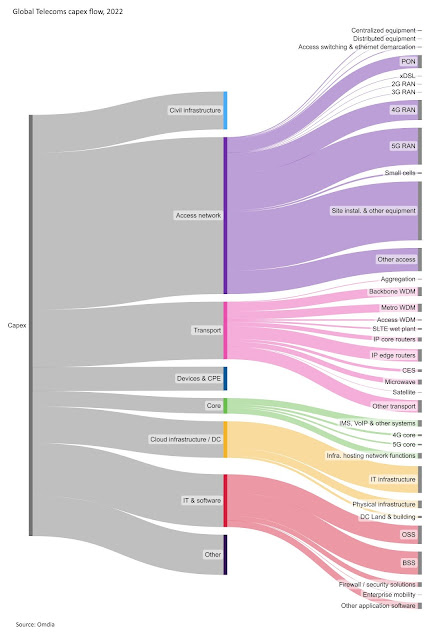
Omdia's Global Telecoms Capex Trends – 2022

Our industry goes through a lot of Mergers and Acquisitions (M&A). Information Handling Services (IHS) built its Technology, Media and Telecoms (TMT) in large part through the acquisition of Infonetics Research for an undisclosed sum in 2014. Then in 2016, IHS merged with London-based Markit to create IHS Markit. Then in 2019, IHS Markit swapped its TMT group with Informa's Agribusiness Intelligence group and $30 million in cash. 

At the start of 2020, Omdia was formed by unifying the depth and breadth of expertise from Informa Tech’s legacy research brands: Ovum, IHS Markit Technology, Tractica and Heavy Reading.

Omdia recently published the 2022 full-year update of its Global Telecoms Capex Tracker, a detailed database of telecom operator capital expenditure (capex) from 1Q19 to 4Q22. This Analyst Opinion covers the major recent developments in telecoms capex and highlights some interesting points from the tracker.

In the tracker, Omdia splits capex estimates into various categories and subcategories that broadly map to our technology market research coverage. For the full year of 2022, the first level of breakdown is into civil infrastructure (9%), access network (37%), transport (14%), core (4%), cloud infrastructure (9%), IT and software (13%), devices and customer premises equipment (CPE) (6%), and other (10%).

You can find the details here. The author, Adam Mackenzie, has shared a high-resolution picture and some more details on his LinkedIn post here. The comments are worth reading as well.

For people who are interested in similar topics, check out the links below 👇.

Related Posts

Friday, 20 May 2022

Vodafone Explains Mobile Phone Mast

Questions related to what does a mobile phone mast consist of keeps popping up time and again. I looked at it some years back but it doesn't stop people asking additional questions. 

When the UK MNOs started their Shared Rural Network journey, Vodafone put together a nice primer on what does a mobile network mast consist of. Here is an extract from the article:

What do all the bits of a mast actually do?

  1. Antenna: Antennas send calls, texts and internet data to your smartphone using radio waves and in turn receive radio waves from it. The higher up an antenna is, the more likely it is that you’ll get a strong and reliable mobile signal from it. Most masts will have at least three antennas to provide coverage in every direction. Masts that need to serve more people, because they’re located in more heavily populated areas, will have more antennas.
  2. Radio unit: The radio unit generates the radio waves transmitted by the antennas. Traditionally, the radio unit was installed at ground level. Nowadays, they’re more likely to be installed higher up the mast closer to the antenna to help improve performance.
  3. Transmission/backhaul: Cables, traditionally copper but now far more likely to be fibre optic, are used to connect the mast with other masts and the rest of the Vodafone network in the UK. These are usually buried in the ground. In a few cases, a microwave dish is used instead.
  4. Cabin/cabinets: Located at ground level, these contain computers which communicate with other masts in the network. Additional equipment, such as a battery backup in case of power failure and connectors for the transmission/backhaul, are also stored here.
  5. Power: Most masts will draw their power from the National Grid; some will have their own renewable power source on-site. In a handful of cases, such as with temporary masts, power will instead be provided by a diesel generator.
  6. Microwave dish: In some locations, such as remote rural areas, a microwave satellite dish is used instead of fibre optic cables to act as transmission/backhaul, connecting the mast to the rest of Vodafone’s network. To do so, the dish must be within line of sight of a dish on another mast.

Why can’t you build it somewhere else?

Not all sites are suitable. To provide the strongest mobile signal to as wide an area as possible, there can’t be too many neighbouring buildings, trees or other geographical features in the way. These tend to block the mast’s signal.

Masts also need their own power and what’s known as “backhaul” – data connections to the rest of the network. To meet soaring demand for faster speeds, that backhaul often consists of fibre optic cables under the ground – it’s a common misconception that most of Vodafone UK’s masts communicate wirelessly with the rest of the network.

And to run these power and data lines to a mast, we have to negotiate with the owners of the land, and quite often, with the owners of land adjacent to it. Those negotiations aren’t just about how much rent we will pay, but how easily we can access those sites for construction, maintenance and repairs.

These so-called “wayleave” negotiations can take time – and sometimes break down completely – setting back mast construction by several months.

Why can’t you just build a shorter, less conspicuous mast?

The taller the mast, the wider the area it can cover and the more people it can provide with a fast and reliable mobile signal. Under current rules, most UK masts are around 25m (82ft) tall. But in fact 50m masts would provide a better, more far-reaching signal in many areas.

Update April 2021 – the UK Government has proposed rule changes that would allow new and existing masts to be up to five metres taller and two metres wider than they currently can be. This would not only help increase the range of their wireless signal, it would also make it easier for masts to be potentially shared with other mobile network operators, as more equipment can be fitted onto taller masts.

Who decides where masts are built?

Our engineers pick sites that best meet the technical, logistical and economic requirements for hosting a mast, but the local council has to grant planning permission for the building works to go ahead. So councils hold public consultations before making their decision and residents can have their say.

You can read the complete article here.

The old video of cell tower construction site is worth a watch and is embedded below:

Related Posts

Sunday, 27 February 2022

Rakuten Mobile shows off their Open RAN Portfolio

(Click on image to enlarge)

During the Full Year and Fourth Quarter 2021 earning call, President of Rakuten Mobile, Yoshihisa Yamada gave a short summary of the progress of the mobile network. During that, he also showed the Open RAN product portfolio spanning to address diverse deployment use cases.

The portfolio can be seen in the picture above and you can listen to his part of the talk in the video below: 

You can download the slides from here.

Related Posts

Friday, 18 February 2022

UK will make Street Furniture accessible for Telecoms Infrastructure

The UK government has announced new plans to slash red tape from 5G roll out and improve mobile phone connectivity. For this to happen, street lights, bus shelters and traffic lights will be allowed host more mobile network equipment thereby helping boost mobile coverage as part of a new scheme to cut red tape and install more 4G and 5G kit.

The following is from the press release:

Eight winning projects will receive a share from the £4 million Digital Connectivity Infrastructure Accelerator (DCIA) to explore how digital software can help simplify local authority processes when telecoms operators request access to publicly-owned buildings and curbside infrastructure.

Street furniture such as road signs and CCTV poles can be used to improve 4G coverage but they are also integral to the roll out of 5G, which requires a larger number of smaller ‘cell sites’ - where antennas and other telecoms equipment are placed to form a network - to ensure seamless coverage and to meet surging demand for connectivity.

However, telecoms firms can often find it difficult and time consuming to acquire the information needed to verify a structure is suitable for hosting network equipment - such as its location, physical dimensions, proximity to the street or access to a power source - which is slowing down the pace of deployment.

In response, the government will invest in piloting the latest innovations in digital asset management platforms. This software will enable local councils to more easily share data mobile companies need to accelerate their roll out plans and deliver the revolutionary benefits of 4G and 5G to people and businesses.

From what we can see, this news has been well received by operators.

Related Posts:

Sunday, 10 October 2021

Multi-sectorised sites and Small Cells help O2 UK handle Capacity in Busy Areas

Radio planning becomes essential in dense urban areas where operators don't only have to serve the highly mobile users but also slow moving pedestrians and users indoors. One some location in London, UK, is O2 UK's highest capacity Nokia site with six-sector low-band LTE in 800 and 900MHz in addition to high-band 4T4R L18/L21, 8T8R L23 as well as standard n78 8T8R 5G.

The site also features numerous high-end Commscope antennas with dual-beam panels that are needed to create six-sector LTE 800 and 900 MHz and then 24 port antennas that carry all the other including 8T8R 2300 MHz, 1800 MHz, 2100 MHz as well as n78 8T8R.

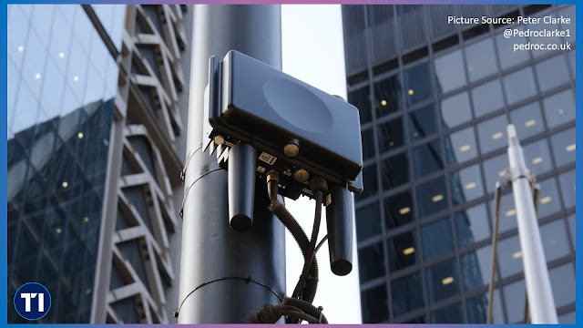
In addition, O2 has multitude of Nokia Small cells sprinkled across the City of London. While these come in all different shape and configurations. In many locations there are ones with directional antennas while there are others with omni-directional antennas as well.

The small cells are located on their own poles, rather than lamp posts and many of these also feature Wi-Fi access points as additional means to alleviate the capacity crunch. In fact they can also be mounted on-top of phone boxes, shops, side of buildings, etc. 

If this is an area of interest and you enjoyed reading the post above, you will no doubt enjoy watching this short video from Peter Clarke who has a great collection of infrastructure from UK and Ireland on his website here. Video as follows:

Related Posts

Saturday, 26 June 2021

Vodafone UK's 5G Infrastructure


Ker Anderson, Head of Radio and Performance, Vodafone UK did an IET presentation looking at Vodafone's infrastructure, especially 5G infrastructure. The video from that has been publicly shared so it is embedded below.

Related Posts:

Friday, 18 June 2021

Cell-Site Construction And Evolution Strategies


We all agree that cell sites are complex beasts. The diagram above shows in a simple way all the tasks that may be necessary for cell site deployment. Late last year, ABI Research produced a whitepaper on "Global Cell-Site Construction And Evolution Strategies" that they made freely available here. Quoting the executive summary below:

5G networks are being rapidly deployed around the world with many of these networks working in parallel to existing legacy cellular technologies, such as 2G/3G and 4G, to provide higher data connections of 10X more throughput than 4G. 5G networks typically use high-frequency spectral resources (C-band and mmWave) and, according to the International Mobile Telecommunications 2020 (IMT-2020), the downlink and uplink peak data rate of a 5G network should be 20 Gigabits per Second (Gbps) and 10 Gbps, respectively, with downlink and uplink peak cell spectral efficiency of 30 bit/Second (s)/Hertz (Hz) and 15 bit/s/Hz, respectively. The use of higher frequency bands, which suffer from higher penetration loss and the continuous increase in requested data rates for end users, dictate the necessity of higher network availability and network capacity, which could be achieved through additional spectral resources and network densification. Many MNOs have already bought at auction spectrum for 5G deployment, but the network capacity can be maximized through network densification. Thus, the acquisition of cell site assets is critical for Mobile Network Operators (MNOs) for the effective performance of 5G networks.

These network requirements have brought huge challenges to MNOs, local governments, vendors, and System Integrators (SI), as some of those challenges are well-known unsolved issues evidenced by the deployment of legacy generations of cellular technologies and have become even more relevant now with the advent of 5G and the expected large-scale cell site densification.

These challenges range from the high cost associated with deploying network infrastructure at street level, to complex approval processes from local government, including lengthy and expensive site acquisition processes; lack of power availability; limited backhaul availability; lengthy planning application processes for street works or build works; limited space availability on premises and within street furniture; size and flexibility of existing cellular equipment that can fit the different rollout scenarios (e.g., smaller antennas to fit within wall-mounted small cell enclosures); lack of availability of underground space for the deployment of a new chamber and ducts; decluttering policies from local governments that can largely impact the deployment of 5G networks; and increasing tenancy fees for additional 5G equipment and increased power supply.

In response to this situation, there is some pressure on telecom equipment vendors to come forward with solutions that suit each rollout scenario. Improved physical features, such as smaller form factor antennas similar to the Wi-Fi Access Points (APs), lighter-weight and smaller Massive Multiple Input, Multiple Output (mMIMO) antennas, and an innovative variety of vendor equipment, backhaul, and reduced power consumption solutions will help MNOs address these challenges and stay ahead of the competition.

Finally, unlike previous generations of cellular technologies, policymakers, urban planners, and local governments have an important role to play, providing more flexible legislation that enable the rollout of network infrastructure at a faster speed by providing clear guidelines for easy access to the assets for the deployment of cellular infrastructure.

While many topics have been covered in the whitepaper, one of the issues I have closely experiences is the insufficient power for the new upgrades. Again, quoting from the whitepaper:

ENERGY

When deploying a cell site, the power requirement can typically be categorized as: 1) static power consumption, which is associated with the support system of a base station, and 2) dynamic power consumption, which is associated with the data traffic load. For a cell site, the amount of energy consumption varies depending on the amount of equipment and the number of frequency bands supported. Optimizing energy consumption can help operators lower their OPEX and achieve environmental goals.

CHALLENGES

Insufficient DC power capacity. Energy consumption is expected to increase with 5G deployments. New frequency bands and an increased number of equipment contribute to the this. Research on developed markets indicates that the maximum power consumption of a typical site supporting five bands could exceed 10 Kilowatts (kW). However, the reality is that about 30% of macrocell sites do not have a power supply that could support such power requirements. The common solution for energy expansion is adding more rectifiers or more energy cabinets. However, the equipment room or cabinet do not always have sufficient space for additional equipment. To cater to the increasing demand for energy, operators need to either find solutions that improve the existing equipment’s efficiency or construct new cabinets at sites. However, newly constructed cabinets also entail increased civil work and rental costs for operators.

Grid reconstruction. Grid power for the existing sites may be insufficient, especially due to the increase in power consumption with a 5G deployment. Such sites need grid modernization, which can be expensive and can greatly slow down the pace of a 5G deployment. Due to the process and construction requirements, the time to modernize the grid could be up to a year for each site.

Insufficient power backup. Operators need to meet the strict five nines or high availability of services. Ensuring business continuity is crucial for any operator. In times of prolonged bad weather or a power outage, grid and solar energy might not be available to power the cell site. Energy storage systems with lead-acid or lithium-ion batteries, for example, are required to mitigate the risk of a power outage. Most existing networks are still using lead-acid batteries, while the low-energy density, heavy weight, and big volume of a lead-acid battery make it difficult to do an expansion when deploying 5G.

High electricity cost. Another key challenge for operators is how to optimize energy efficiency, translating into good investments by operators. Relying solely on the electric grid could result in high energy expenditure, and the need to consider multiple energy resources. Traffic usage is also not constant throughout the day and varies depending on the location (e.g., city centers versus suburbs). How operators can manage the energy system intelligently and efficiently to reduce unnecessary waste becomes a core consideration.

Given the rapid development of 5G technology and an increasing host of service applications, computing is getting closer to users, with communication technologies and information technologies evolving toward converged Information and Communications Technology (ICT) architecture at an ever-faster pace. The increasing applications and computing required at the edge means that the power supply demand is expected to increase. Therefore, it is necessary to consider the amount of Alternating Current (AC)/Direct Current (DC) power supply needed at the cell site, as well as the number of equipment rooms that are required.

The paper goes on to describe the solutions. You can download the paper here.

If you have a favourite cell site issue do let us know in the comments.

Related Posts:

Friday, 4 June 2021

Three UK's Gigabit 5G Poles Explained


Peter Clarke does a great service to the mobile industry, especially in UK, with his detailed look at the mobile network's infrastructure. 

Three UK was Huawei shop but after the limitations imposed on them, they moved to Ericsson and announced with a big bang.

When they said in December that they will have 1000 5G sites, many were left wondering how many of those would be Huawei and Ericsson

But they did make a fantastic progress transitioning to E///

Now Peter has made a video detailing the Ericsson Three UK sites. It has a lot of useful information and is embedded below.

Let us know what do you think.

Related Posts:

Saturday, 3 April 2021

Transition to Infrastructure 2.0

Infrastructure can mean different things to different people in different industries. We tried to explain what it means in the telecoms industry in one of our tutorials here.

When it comes to Infrastructure 2.0, there are articles dating back years. Couple of examples here and here. Back in those days we were talking more about virtualization while today we are talking about containerization and cloudification. We have some introductory presentations on Cloud Native here.

I have heard Qualcomm speakers talk about Infrastructure 2.0 but what does it mean from their point of view? Here is what Cristiano R. Amon, President & CEO-Elect of Qualcomm meant according to RCR Wireless

Infrastructure 2.0 seeks to address the fact that existing core network infrastructure is limited in its ability to handle the highly virtualized network models that the industry is moving toward.

For instance, there has been some concern for awhile now around how data center virtualization will impact existing enterprise networking models.

At the CTIA event, Amon explained that 5G will be revolutionary, creating new industries, use cases, services and network models. However, a network capable of doing all that 5G promises requires “infrastructure like we’ve never seen.”

“It needs to be dense, high-performance, cost-effective and power-efficient for both indoors and outdoors, and support public and private networks with a scalable and flexible networking equipment for diverse deployments across multiple industries and use cases,” he continued. “This modern 5G network is driving a shift towards virtualized radio access solutions or vRAN.”

For further context, in a previous conversation with RCR Wireless News, Amon discussed how this push towards virtualization and openness is a potential vector of disruption to traditional network equipment providers, and this disruption is what will lead to Infrastructure 2.0.

“I believe that vRAN and Open RAN creates a huge opportunity for some of the network equipment providers that will lead the transition in what Infrastructure 2.0 is,” he said, adding that incumbents could “take a leading role in the software that will run in those networks and will provide feature parity between the existing systems and the new systems.”

With the announcement of Qualcomm 5G RAN platforms, we will probably seem them talking a lot more about Infrastructure 2.0

Related Posts:

Thursday, 26 November 2020

NTT Docomo's 5G RAN Infrastructure

We looked at NTT Docomo's 5G Journey and 5G Network Deployment details recently here. In this post we will look at the 5G Infrastructure that Docomo is using in their network. It is detailed in their latest Technical Journal here. In this post we will look at the infrastructure part only.


The 5G network configuration is shown in Figure 4. With a view to 5G service development, NTT DOCOMO developed a Central Unit (CU) that consolidates the Base Band (BB) signal processing section supporting 5G, extended existing BB processing equipment known as high-density Base station Digital processing Equipment (BDE), and developed a 5G Radio Unit (RU) having signal transmit / receive functions. Furthermore, to have a single CU accommodate many RUs, NTT DOCOMO developed a 5G version of the FrontHaul Multiplexer (FHM) deployed in LTE. Each of these three types of equipment is described below.

1) CU
(a) Development concept: With the aim of achieving a smooth rollout of 5G services, NTT DOCOMO developed a CU that enables area construction without having to replace existing equipment while minimizing the construction period and facility investment. This was accomplished by making maximum use of the existing high-density BDE that performs BB signal processing, replacing some of the cards of the high-density BDE, and upgrading the software to support 5G.

(b) CU basic specifications: An external view of this CU is shown in Photo 1. This equipment has the features described below (Table 3). As described above, this equipment enables 5G-supporting functions by replacing some of the cards of the existing high-density BDE. In addition, future software upgrades will load both software supporting conventional 3G/LTE/LTE-Advanced and software supporting 5G. This will enable the construction of a network supporting three generations of mobile communications from 3G to 5G with a single CU.

The existing LTE-Advanced system employs advanced Centralized RAN (C-RAN) architecture proposed by NTT DOCOMO. This architecture is also supported in 5G with the connection between CU and RUs made via the fronthaul. Standardization of this fronthaul was promoted at the Open RAN (O-RAN) Alliance jointly established in February 2018 by five operators including NTT DOCOMO.  Since the launch of 5G services, the fronthaul in the NTT DOCOMO network was made to conform to these O-RAN fronthaul specifications that enable interoperability between different vendors, and any CU and RU that conform to these specifications can be interconnected regardless of vendor. The specifications for inter-connecting base-station equipment also con-form to these O-RAN specifications, which means that a multi-vendor connection can be made between a CU supporting 5G and a high-density BDE supporting LTE-Advanced. This enables NTT DOCOMO to deploy a CU regardless of the vendor of the existing high-density BDE and to quickly and flexibly roll out service areas where needed while making best use of existing assets. In addition, six or more fronthaul connections can be made per CU and the destination RU of each fronthaul connection can be se-lected. Since 5G supports wideband trans-mission beyond that of LTE-Advanced, the fronthaul transmission rate has been extend-ed from the existing peak rate of 9.8 Gbps to a peak rate of 25 Gbps while achieving a CU/RU optical distance equivalent to that of the existing high-density BDE.

2) RU
(a) Development concept: To facilitate flexible area construction right from the launch of 5G services, NTT DOCOMO developed the low-power Small Radio Unit (SRU) as the RU for small cells and developed, in particular, separate SRUs for each of the 3.7 GHz, 4.5 GHz, and 28 GHz frequency bands provided at the launch of the 5G pre-commercial service in September 2019. Furthermore, with an eye to early expansion of the 5G service area, NTT DOCOMO developed the Regular power Radio Unit (RRU) as the RU for macrocells to enable the efficient creation of service areas in suburbs and elsewhere.

A key 5G function is beamforming that aims to reduce interference with other cells and thereby improve the user’s quality of experience. To support this function, NTT DOCOMO developed a unit that integrates the antenna and 5G radio section (antenna-integrated RU). It also developed a unit that separates the antenna and 5G radio section (antenna-separated RU) to enable an RU to be placed alongside existing 3G/LTE/LTE-Advanced Radio Equipment (RE) and facilitate flexible installation even for locations with limited space or other constraints.

(b) SRU basic specifications: As described above, NTT DOCOMO developed the SRU to enable flexible construction of 5G service areas. It developed, in particular, antenna-integrated SRUs to support each of the 3.7 GHz, 4.5 GHz, and 28 GHz frequency bands provided at the launch of the 5G pre-commercial service and antenna-separated SRUs to support each of the 3.7 GHz and 4.5 GHz frequency bands (Photo 2). These two types of SRUs have the following features (Table 4).

The antenna-integrated RU is equipped with an antenna panel to implement the beamforming function. In the 3.7 GHz and 4.5 GHz bands, specifications call for a maximum of 8 beams, and in the 28 GHz band, for a maximum of 64 beams. An area may be formed with the number of transmit/receive beams tailored to the TDD Config used by NTT DOCOMO. In addition, the number of transmit/receive branches is 4 for the 3.7 GHz and 4.5 GHz bands and 2 for the 28 GHz band, and MIMO transmission/reception can be performed with a maximum of 4 layers for the former bands and a maximum of 2 layers for the latter band.

The antenna-separated SRU is configured with only the radio as in conventional RE to save space and facilitate installation. With this type of SRU, the antenna may be installed at a different location. Moreover, compared to the antenna-integrated SRU operating in the same frequency band, the antenna-separated SRU reduces equipment volume to 6.5ℓ or less. The antenna-separated SRU does not support the beamforming function, but features four transmit/receive branches the same as the antenna-integrated SRU for the same frequency band.

(c) RRU basic specifications: The RRU was developed in conjunction with the 5G service rollout as high-power equipment compared with the SRU with a view to early expansion of the 5G service area (Photo 3). This type of equipment has the following features (Table 5).


Compared with existing Remote Radio Equipment (RRE) for macrocells, the volume of RRU equipment tends to be larger to support 5G broadband, but in view of the latest electronic device trends, NTT DOCOMO took the lead in developing and deploying an antenna-separated RRU that could save space and reduce weight. Maximum transmission power is 36.3 W/100 MHz/branch taking the radius of a macrocell area into account. The RRU features four transmit/receive branches and achieves the same number of MIMO transmission/reception layers as the antenna-separated SRU.
NTT DOCOMO also plans to deploy an antenna-integrated RRU at a later date. The plan here is to construct 5G service areas in a flexible manner making best use of each of these models while taking installation location and other factors into account.

3) 5G FHM
The 5G FHM is equipment having a multiplexing function for splitting and combining a maximum of 12 radio signals on the fronthaul. It was developed in conjunction with the 5G service rollout the same as RRU (Photo 4).
If no 5G FHM is being used, each RU is accommodated as one cell, but when using a 5G FHM, a maximum of 12 RUs can be accommodated as one cell in a CU. At the launch of 5G services, this meant that more RUs could be accommodated in a single CU when forming a service area in a location having low required radio capacity (Figure 5). Additionally, since all RUs transmit and receive radio signals of the same cell, the 5G FHM can inhibit inter-RU interference and the occurrence of Hand-Over (HO) control between RUs as in the conventional FHM. Furthermore, the 5G FHM supports all of the 5G frequency bands, that is, the 3.7 GHz, 4.5 GHz, and 28 GHz bands, which means that service areas can be constructed in a flexible manner applying each of these frequency bands as needed.

All the fronthaul and other interfaces that Docomo used in their network was based on O-RAN alliance specifications. In a future post, we will look at some of the details.

Related Posts